System component description
31
EMC® VNX5300™ Hardware Information Guide
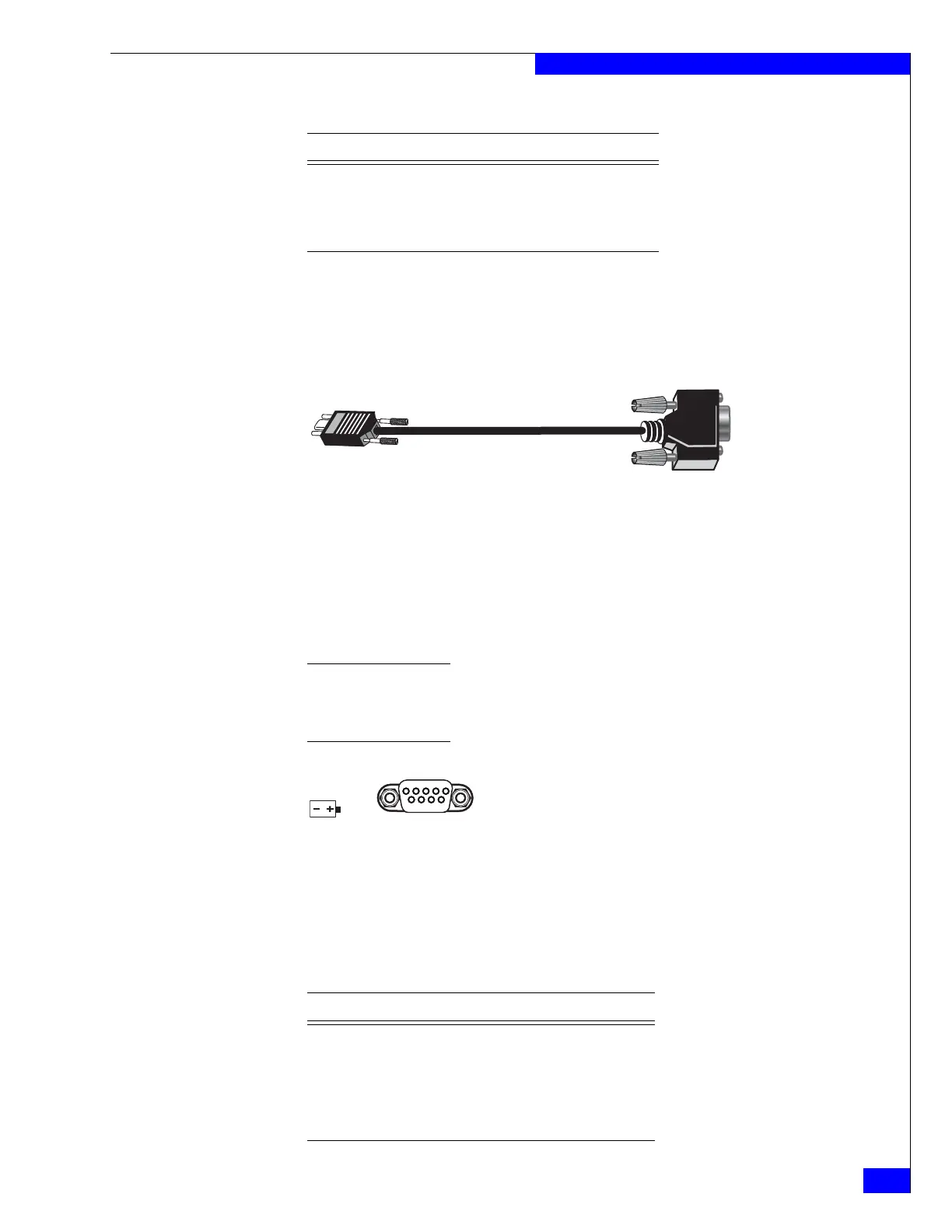
SP null modem (micro DB-9 to DB-9 serial) cable
The cable connecting the SP to the PC or service laptop is a micro DB-9 cable (plug) to
serial DB-9 (socket). It has a micro DB-9 plug (SP side) on one end and a serial DB-9
socket (PC or service laptop side) on the other end. Figure 27 shows an example of an
SP to PC (service laptop) cable.
Figure 27 Example of SP null modem (micro DB-9) to serial (DB-9) cable
Serial RS-232/EIA 232 (micro DB-9) connector (socket) for SPS management
The back of the Block and File VNX5300 platform SP includes a second standard
serial RS-232/EIA 232 interface (micro DB-9) socket connector (labeled with a symbol
depicting a battery to the left) to connect to the SPS management port (RJ-12). Notice
the orientation of the pins shown in Figure 28.
Note: The included cable has a micro DB-9 connector (pins 1, 3, and 4 are used) on one end and
an RJ-12 modular jack adapter (pins 1, 7, and 8 are used) on the other end. The RJ-12 modular
jack adaptor end connects to the RJ-12 modular jack connector on the SPS (Figure 14 on
page 20).
Figure 28 Serial RS-232/EIA 232 (micro DB-9) connector (socket)
Table 20 lists the SP serial RS-232/EIA 232 (micro DB-9) pin signals used on the
connector.
7 RTS Request to send
8 CTS Clear to send
9 RI Ring indicator
Table 19 Serial RS-232/EIA 232 (micro DB-9) connector (socket) pinout (continued)
DB-9 Pin Signal Description
VNX-000093
Table 20 Serial RS-232/EIA 232 (micro DB-9) connector (socket) pinout
DB-9 Pin Signal Description
1 CD Carrier detect
2 RXD Received data
3 TXD Transmitted data
4 DTR Data terminal ready


 To Next Page