11
PID Mode.
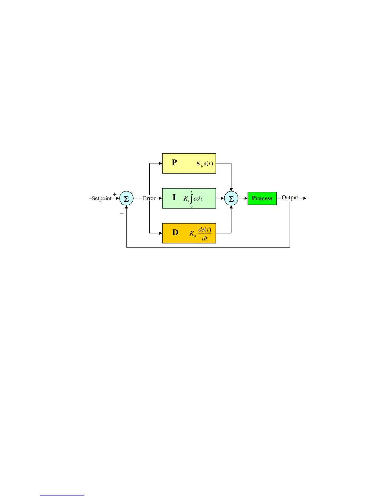
A proportional–integral–derivative controller (PID controller) is a generic control loop feedback mechanism.
PID controller attempts to correct the error between a measured process variable and a desired setpoint by calculating
and then outputting a corrective action that can adjust the process accordingly.
The PID controller calculation (algorithm) involves three separate parameters; the Proportional, the Integral and
Derivative values. The Proportional value determines the reaction to the current error, the Integral determines the
reaction based on the sum of recent errors and the Derivative determines the reaction to the rate at which the error has
been changing. The weighted sum of these three actions is used to adjust the process. By “tuning” the three constants
in the PID controller algorithm the PID can provide control action designed for specic process requirements. The
response of the controller can be described in terms of the responsiveness of the controller to an error, the degree to
which the controller overshoots the setpoint and the degree of system oscillation. Note that the use of the PID algorithm
for control does not guarantee optimal control of the system or system stability.
(K
p
) is the constant proportional gain
(K
i
) is the constant integral gain
(K
d
) is the constant derivative gain
(e): error
(t): Time in the past contributing to the integral response
Parameters to set for this mode are:
IN: assign “input” number then edit the name by moving wheel. If the “input” number is already used then it will not be
shown. Choose “X” instead of a number to disable input.
RL: assign “relay” number then edit the name by moving wheel. If the “relay” number is already used then it will not be
shown. Choose “X” instead of a number to disable relay.
STOP: (“ON”: when product into tank is ending, then the related output will be off and an alarm condition will pop-up.
“OFF”: when product into tank is ending, then the related output will continue to stay on and an alarm condition will pop-up.)
ON: Activate RL and LEV on moving proportionally towards the unit value (for example: pH)
OFF: Disable RL and LEV on moving proportionally towards the unit value (for example: pH)
I: integral time (from 0s to 59m:59s)
D: derivative time (from 0s to 59m:59s)
g. 6