36
Appendix A - Probes Connections.
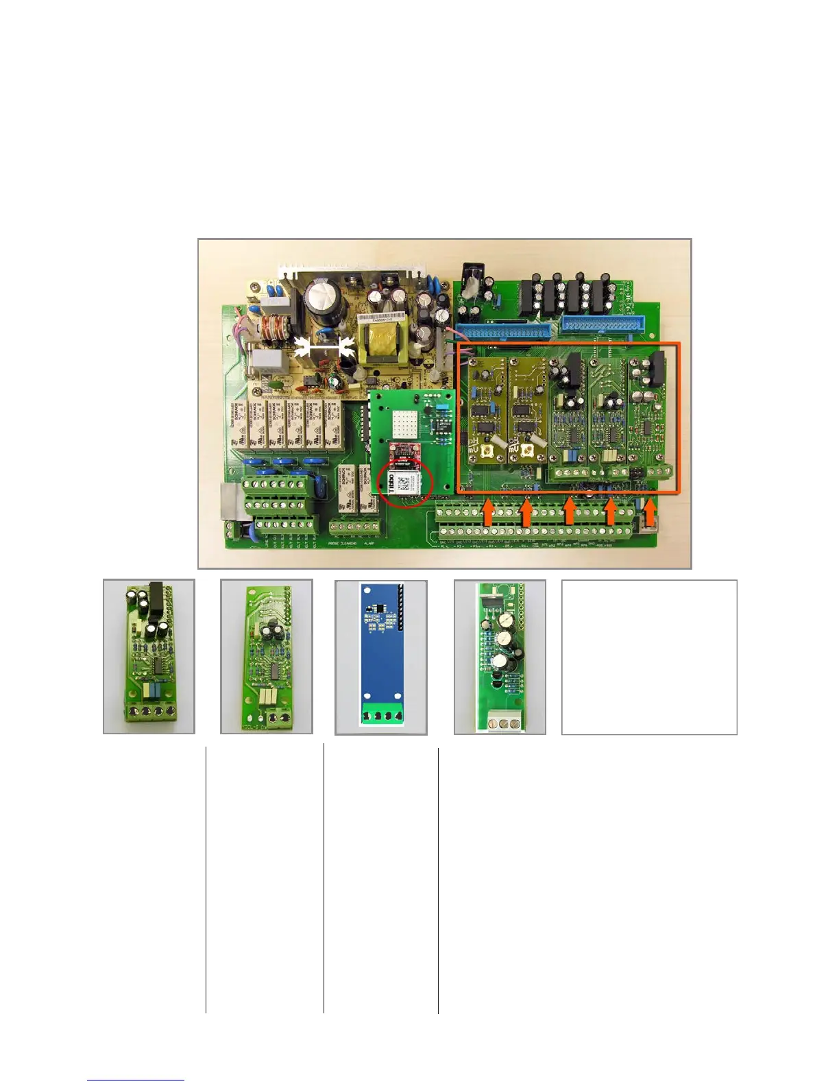
Located in upperside of mainboard there are four connectors that can be used to install probe modules. Modules
come pre-installed upon request and may appear different as shown (different congurations). Identify installed modules
to correctly connect probes. For Ethernet version a standard ethernet cable (RJ45) is required.
MDCL-6
1 2
MDCL-1
1 2 3 4
Module suitable for:
ECL1
ECL2
ECL3
ECL8
ECL9
ECL10
ECL11
ECL17
ECL18
Connect probe as follows:
Block n.1 : Brown(+) wire
Block n.2 : White(-) wire
Block n.3 : Green(IN) wire
Block n.4 : Yellow(GND) wire
Module suitable for:
ECL4
ECL5
ECL6
ECL7
Connect probe as follows:
Block n.1 : Black(-) wire
Block n.2 : Red (+) wire
ETHERNET
CONNECTOR
CH1 CH2 CH3 CH4 CH5
CHLORINE module
Probes conguration
for “MAX5 PH CL PH CL double
FLOW”
model only
Ch1: PH1
Ch2: CL1
Ch3: PH2
Ch4: CL2
Ch5: Temp1
Temp1 is related to PH1 / CL1
Temp2 is related to PH2 / CL2
1 2 3
Module suitable for:
Temperature probe
Temp1 ( “MAX5 PH CL PH CL double ow” model only)
Connect as follows:
Block n.1 : Red wire
Block n.2 : White wire
Block n.3 : Black wire
TEMP1
MDSCL
Module suitable for:
SCLxx probes
Connect probe
as follows:
1 (-485) green wire
2 (+485) white wire
3 (GND) black wire
4 (+5VDC) red wire
1 2 3 4