Quick Installation Guide
00825-0100-4001, Rev BA
November 2002
Model 3051
STEP 4: CONNECT THE WIRING AND POWER UP
Use the following steps to wire the transmitter:
1. Remove the housing cover on the side marked FIELD
TERMINALS.
2. Connect the positive lead to the "+" terminal, and the negative lead
to the "–" terminal.
NOTE
Do not connect the powered signal wiring to the test terminals. Power
could damage the test diode in the test connection. Shielded, twisted
pair cable should be used for best results. Use 24 AWG or larger wire
and do not exceed 5,000 feet (1 500 meters).
3. Plug and seal unused conduit connections.
4. If applicable, install wiring with a drip loop. Arrange the drip loop
so the bottom is lower than the conduit connections and the
transmitter housing.
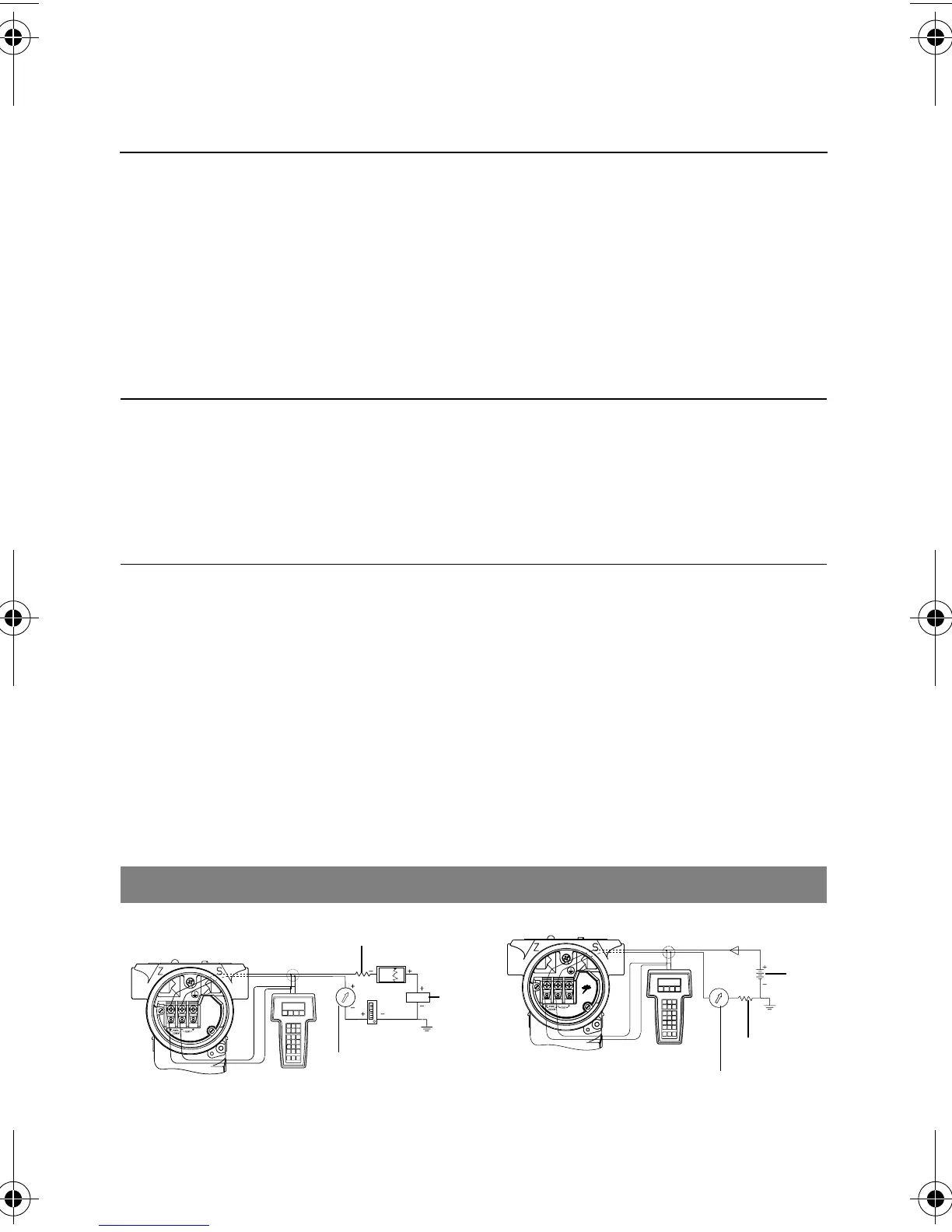
Figure 2 shows wiring connections necessary to power a Model 3051
and enable communications with a hand-held HART communicator.
For low-power transmitters, refer to the reference manual.
Figure 2. Transmitter Wiring Diagrams
Wiring in the Field Transient Wiring
Installation of the transient protection terminal block does not provide
transient protection unless the Model 3051 case is properly grounded.
Current
Meter
RL ≥ 250 Ω
Power
Supply
RL ≥ 250 Ω
Current Meter
24 V dc
Supply
4001_RevBA.fm Page 6 Monday, November 25, 2002 2:27 PM
 Loading...


