Menu 9 Introduction
Parameter
x.00
Parameter
description format
Keypad and
display
Serial
communications
CT Modbus
RTU
PLC Ladder
programming
CTSoft Menu 0
Advanced parameter
descriptions
124 Commander SK Advanced User Guide
www.controltechniques.com Issue Number: 9
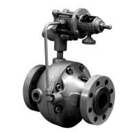
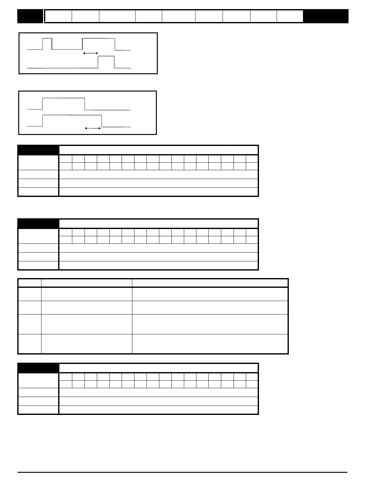
the delay time as shown below.
If the delay parameter is negative, the delay holds the output active for the delay period after the active condition has been removed as shown below.
Therefore an active input that lasts for as long as the sample time or more will produce an output that lasts at least as long as the delay time.
This destination parameter and Pr 9.10 define the parameters to be controlled by the logic function. Only non-protected parameters can be
programmed as a destination. If a invalid parameter is programmed, the output is not routed anywhere.
The motorized pot modes are given in the table below:
When this bit is set to OFF(0) the motorized pot output is limited to positive values only (0 to 100.0%). Setting it to On(1) allows negative outputs also
(-100.0% to 100.0%).
9.20 Logic function 2 destination
Coding
Bit SP FI DE Txt VM DP ND RA NC NV PT US RW BU PS
2 1111
Range Pr 0.00 to Pr 21.51
Default Pr 0.00
Update rate Read on drive reset
9.21 Motorized pot mode
Coding
Bit SP FI DE Txt VM DP ND RA NC NV PT US RW BU PS
111
Range 0 to 3
Default 2
Update rate Background read
Pr 9.21 Mode Comments
0 Zero at power-up
Reset to zero at each power-up.
Up, down and reset are active at all times.
1 Last value at power-up
Set to value at power-down when drive powered-up.
Up, down and reset are active at all times.
2
Zero at power-up and only change
when drive running
Reset to zero at each power-up.
Up and down are only active when the drive is running (i.e. inverter
active). Reset is active at all times.
3
Last value at power-up and only
change when drive running
Set to value at power-down when drive powered-up.
Up and down are only active when the drive is running (i.e. inverter
active). Reset is active at all times.
9.22 Motorized pot bipolar select
Coding
Bit SP FI DE Txt VM DP ND RA NC NV PT US RW BU PS
111
Range OFF(0) or On(1)
Default OFF(0)
Update rate 21 ms