Introduction
Parameter
x.00
Parameter
description format
Keypad and
display
Serial
communications
CT Modbus
RTU
PLC Ladder
programming
CTSoft
Parameter
x.00
Advanced parameter
descriptions
Commander SK Advanced User Guide 17
Issue Number: 9 www.controltechniques.com
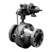
The master must implement a message time out to handle transmission errors. This time out period must be set to the maximum slave response time
+ transmission time for the response.
6.1.2 Slave address
The first byte of the frame is the slave node address. Valid slave node addresses are 1 through 247 decimal. In the master request this byte indicates
the target slave node; in the slave response this byte indicates the address of the slave sending the response.
Global addressing
Address zero addresses all slave nodes on the network. Slave nodes suppress the response messages for broadcast requests.
6.1.3 MODBUS registers
The MODBUS register address range is 16bit (65536 registers) which at the protocol level is represented by indexes 0 through 65535.
PLC registers
Modicon PLCs typically define 4 register 'files' each containing 65536 registers. Traditionally, the registers are referenced 1 through 65536 rather than
0 through 65535. The register address is therefore decremented on the master device before passing to the protocol.
The register file type code is NOT transmitted by MODBUS and all register files can be considered to map onto a single register address space.
All parameters in the drive are holding registers.
CT parameter mapping
All CT products are parameterized using the menu.param notation. Indexes 'menu' and 'param' are in the range 0 through 99. The menu.param is
mapped into the MODBUS register space as menu*100 + param.
To correctly map the parameters at the application layer, the slave device increments the received register address. The consequence of this
behaviour is that Pr 0.00 cannot be accessed.
Data types
The MODBUS protocol specification defines registers as 16bit signed integers. All CT devices support this data size.
Refer to the section 6.1.8 Extended data types on page 20 for detail on accessing 32bit register data.
6.1.4 Data consistency
All CT devices support a minimum data consistency of one parameter (16bit or 32bit data). Some devices support consistency for a complete multiple
register transaction.
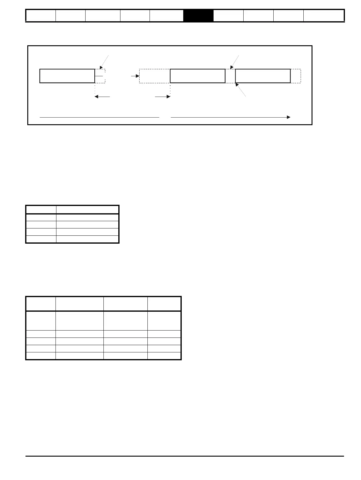
File type Description
1 Read only bits
2 Read / write bits
3 Read only 16bit register
4 Read / write 16bit register
CT
parameter
MODBUS PLC
register
Register address
(protocol level)
Comments
X.Y 40000 + X x 100 + Y X x 100 + Y - 1
Pr 0.00
cannot be
accessed
Examples:
Pr 1.02 40102 101
Pr 1.00 40100 99
Pr 0.01 40001 0
Master request
Time
frame detect
Slave frame
processing
Slave response
Slave response time
Master request
New master request
can start here
minimum silence
period
minimum silence
period