Menu 15
I/O options
Introduction
Parameter
x.00
Parameter
description format
Keypad and
display
Serial
communications
CT Modbus
RTU
PLC Ladder
programming
CTSoft Menu 0
Advanced parameter
descriptions
172 Commander SK Advanced User Guide
www.controltechniques.com Issue Number: 9
10.15.1 SM-I/O Lite and SM-I/O Timer Solutions Module
The encoder reference function is only active if the output destination is routed to a valid unprotected parameter. If only the indicator parameters are
required, the destination parameter should be routed to an unused valid parameter.
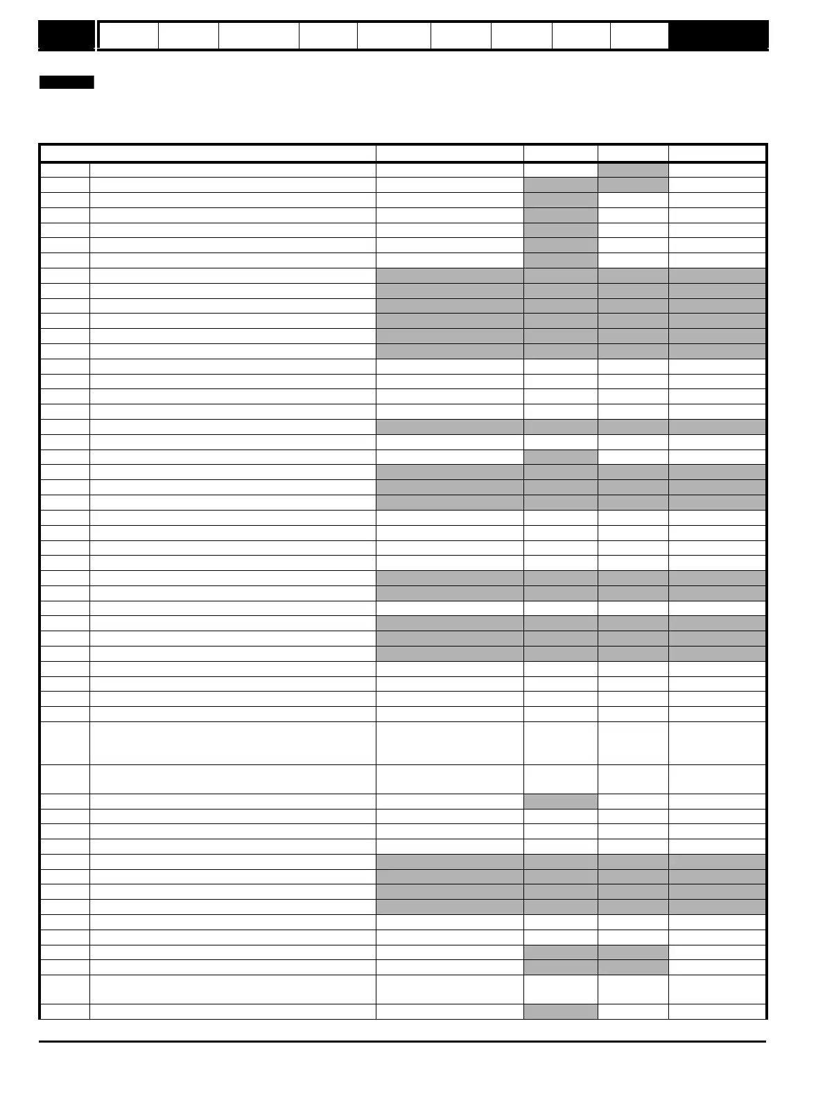
Table 10-27 Menu 15 I/O option parameters: single line descriptions
Parameter Range Default Setting Update Rate
15.01 Solutions Module identification code 0 to 599 See table
Write on power up
15.02 Solutions Module software version 00.00 to 99.99
Write on power up
15.03 Current loop loss indicator
OFF(0) or On(1) BW
15.04 Terminal T5 digital input 1 state
OFF(0) or On(1) BW
15.05 Terminal T6 digital input 2 state
OFF(0) or On(1) BW
15.06 Terminal T7 digital input 3 state
OFF(0) or On(1) BW
15.07 Relay 1 state (Terminals T21 and T23)
OFF(0) or On(1) BW
15.08 Not used
15.09 Not used
15.10 Not used
15.11 Not used
15.12 Not used
15.13 Not used
15.14 Terminal T5 digital input 1 invert OFF(0) or On(1) OFF(0) BR
15.15 Terminal T6 digital input 2 invert
OFF(0) or On(1) OFF(0) BR
15.16 Terminal T7 digital input 3 invert
OFF(0) or On(1) OFF(0) BR
15.17 Relay 1 invert
OFF(0) or On(1) OFF(0) BR
15.18 Not used
15.19 Real time clock daylight saving mode OFF(0) or On(1) OFF(0) BR
15.20 Digital I/O read word
0 to 120 BW
15.21 Not used
15.22 Not used
15.23 Not used
15.24 Terminal T5 digital input 1 destination Pr 0.00 to Pr 21.51 Pr 0.00 Drive reset
15.25 Terminal T6 digital input 2 destination
Pr 0.00 to Pr 21.51 Pr 0.00 Drive reset
15.26 Terminal T7 digital input 3 destination
Pr 0.00 to Pr 21.51 Pr 0.00 Drive reset
15.27 Terminal T21/T23 relay 1 source
Pr 0.00 to Pr 21.51 Pr 0.00 Drive reset
15.28 Not used
15.29 Not used
15.30 Real time clock update mode 0 to 2 0 B R/W
15.31 Not used
15.32 Not used
15.33 Not used
15.34 Real time clock minutes/seconds 00.00 to 59.59 00.00 B R/W
15.35 Real time clock days/hours
1.00 to 7.23 0.00 B R/W
15.36 Real time clock month/date
00.00 to 12.31 00.00 B R/W
15.37 Real time clock years
2000 to 2099 2000 B R/W
15.38 Analog input 1 mode (Terminal T2)
0-20(0), 20-0(1), 4-20(2),
20-4(3), 4-.20(4), 20-.4(5),
VoLt(6)
0-20(0) On Drive reset
15.39 Analog output 1 mode (Terminal T3)
0-20(0), 20-0(1), 4-20(2),
20-4(3), VoLt(4)
0-20(0) BR
15.40 Analog input 1 level (Terminal T2)
-100% to +100% BW
15.41 Analog input 1 scaling (Terminal T2)
0.000 to 4.000 1.000 BR
15.42 Analog input 1 invert (Terminal T2)
OFF(0) or On(1) OFF(0) BR
15.43 Analog input 1 destination (Terminal T2)
Pr 0.00 to Pr 21.51 Pr 0.00 Drive reset
15.44 Not used
15.45 Not used
15.46 Not used
15.47 Not used
15.48 Analog output 1 source (Terminal T3) Pr 0.00 to Pr 21.51 Pr 0.00 Drive reset
15.49 Analog output 1 scaling (Terminal T3)
0.000 to 4.000 1.000 BR
15.50 Solutions Module error status 0 to 255
BR
15.51 Solutions Module software sub-version 0 to 99
Write on power up
15.52 Drive encoder lines per revolution
512(0), 1024(1), 2048(2),
4096(3)
1024(1) BR
15.53 Drive encoder revolution counter
0 to 65535 BW