Introduction
Parameter
x.00
Parameter
description format
Keypad and
display
Serial
communications
CT Modbus
RTU
PLC Ladder
programming
CTSoft Menu 0
Advanced parameter
descriptions
Menu 14
Commander SK Advanced User Guide 167
Issue Number: 9 www.controltechniques.com
The PID function is only active if the output destination is routed to a valid unprotected parameter. If only the indicator parameters are required, the
destination parameter should be routed to an unused valid parameter.
This parameter monitors the output of the PID controller before scaling is applied. Subject to the PID output limits the PID output is given by:
Output = Pe + Ie/s + Des
Where:
P = proportional gain (Pr 14.10)
I = integral gain (Pr 14.11)
D = differential gain (Pr 14.12)
e = input error to the PID (14.22)
s = Laplace operator
Therefore with an error of 100% and P = 1.00 the output produced by the proportional term is 100%. With an error of 100% and I = 1.00 the output
produced by the integral term will increase linearly by 100% every second. With an error that is increasing by 100% per second and D = 1.00 the
output produced by the D term will be 100%.
These parameters define the variables which are to be used as the input variables to the PID controller. Only valid parameters can be programmed as
a source. If a non valid parameter is programmed the input value is taken as 0. All variable inputs to the PID are automatically scaled to variables
having the range of ±100.0% or 0 to 100% (of the source parameter) if they are unipolar.
These parameters can be used to invert the PID reference and source variables respectively.
This parameter defines the time taken for the reference input to ramp from 0.0 to 100.0% following a 0 to 100% step change in input.
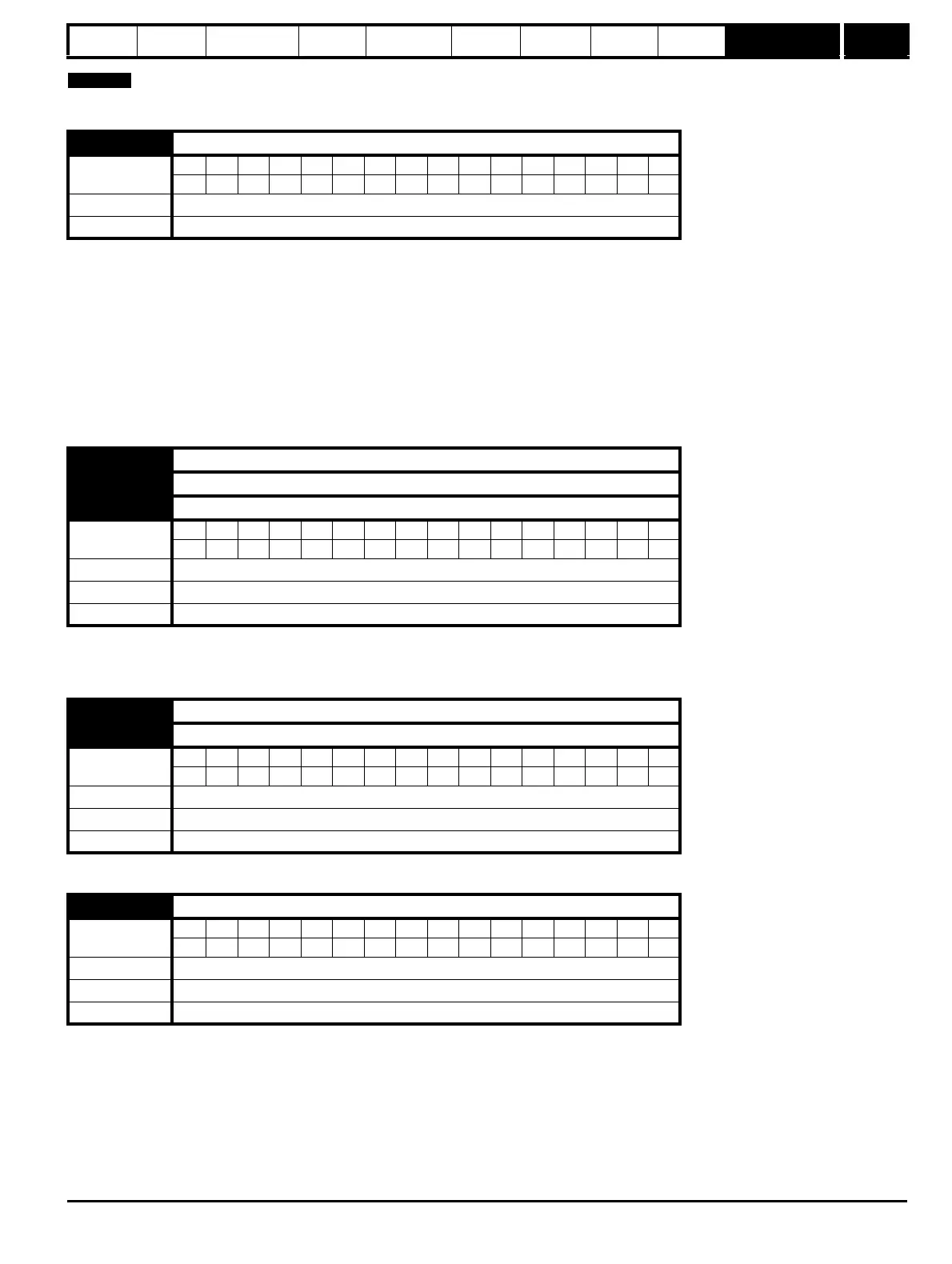
14.01 PID output
Coding
Bit SP FI DE Txt VM DP ND RA NC NV PT US RW BU PS
11 1 1
Range ±100%
Update rate 21 ms
14.02 PID main reference source
14.03 PID reference source
14.04 PID feedback source
Coding
Bit SP FI DE Txt VM DP ND RA NC NV PT US RW BU PS
2 1111
Range Pr 0.00 to Pr 21.51
Default Pr 0.00
Update rate Read on drive reset
14.05 PID reference source invert
14.06 PID feedback source invert
Coding
Bit SP FI DE Txt VM DP ND RA NC NV PT US RW BU PS
111
Range OFF(0) or On(1)
Default OFF(0)
Update rate 21 ms
14.07 PID reference slew rate limit
Coding
Bit SP FI DE Txt VM DP ND RA NC NV PT US RW BU PS
1 111
Range 0.0 to 3200.0 s
Default 0.0
Update rate Background