02/02
10
During normal operation both the rectifier and inverter sections are
active and provides regulated load power whilst simultaneously float
charging the battery. In the event of a mains power failure, the
rectifier becomes inoperative and the inverter is powered solely from
the battery. Critical load power is maintained under these conditions
until the battery is fully discharged, whereupon the UPS shuts down.
The end of a battery discharge is assumed when the battery voltage
falls below a preset value (i.e. 330V d.c. for a 400 V AC system.
The period for which the load can be maintained following a mains
power failure is known as the system’s ‘Autonomy Time’ and is
dependent upon both the battery A/hr capacity and the applied
percentage load. It is usual in larger installations to provide an
alternative UPS input power source from a stand by generator when
the mains supply fails. Once such a generator has been brought on-
line, and the UPS input power has been re-established, the batteries
immediately begin to recharge. Modern generators can be started
and brought on-line very quickly and where such a facility is
incorporated into the UPS installation, it results in short battery
discharge periods and correspondingly rapid recharge times.
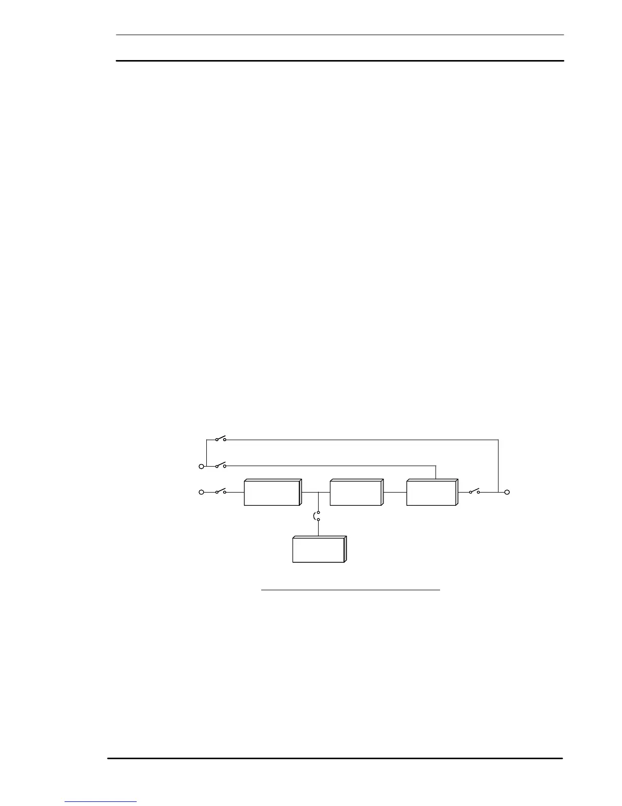
The circuit block annotated ‘Static Switch’ in figure 1-2 contains an
electronically controlled switching circuit which enables the critical
load to be connected either to the inverter output or to a bypass
power source via the ‘static bypass line’. Normally, the load is
connected to the inverter via a static switch circuits but in the event of
a UPS overload, or inverter failure, it is automatically transferred to
the Static bypass line.
To provide a clean (no-break) load transfer between the inverter and
static bypass line, the static switch activates connecting the load to the
bypass supplies followed by inverter static switch opening. To achieve
this, the inverter output and bypass supply must be fully synchronized
during normal operating conditions. This is achieved through the
inverter control electronics which make the inverter frequency track
that of the static bypass supply-provided that the bypass remains
within an acceptable frequency window. The synchronising window
is pre-selected to 2% (selectable upto 9%) of nominal frequency,
giving an acceptable frequency window of ± 1Hz.
RECTIFIER
STATIC
SWITCH
INVERTER
BATTERY
Bypass
a.c.
Supply
Rectifier
Input
a.c.
Supply
UPS
Output
a.c.
Supply
Battery
Circuit
Breaker
Output
Power
Switch Q4
Rectifier
Input
Switch Q1
Maintenance Bypass
Power Switch Q3
Maintenance Bypass Line
Static Bypass Line
Bypass Power Switch Q2
RECTIFIER
STATIC
SWITCH
INVERTER
BATTERY
Bypass
a.c.
Supply
Rectifier
Input
a.c.
Supply
UPS
Output
a.c.
Supply
Battery
Circuit
Breaker
Output
Power
Switch Q4
Rectifier
Input
Switch Q1
Maintenance Bypass
Power Switch Q3
Maintenance Bypass Line
Static Bypass Line
Bypass Power Switch Q2
Figure 1-2: UPS Power Switches Configuration

 Loading...