02/02
20
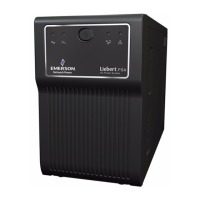
Figure 2-1: LED Indications
A = (Q1) Rectifier Input Power Switch
B = (Q2) Static Bypass Input Power Switch
C = (Q3) Maintenance Bypass Power Switch
D = (Q4) UPS Output Power Switch
1 = Reset Push-button
2 = UPS Logic Boards
Figure 2-2: Power Switch Identification
3
6
8
1
2 4 5 97
3
6
8
1
2 4 5 97
A
B
C
D
1
2
A
B
C
D
1
2

 Loading...