August 2016
Installation and Operation Manual
Part Number: VA001-507-32, Rev. 1
34
Section 5: Operation
Operation
NOTE:
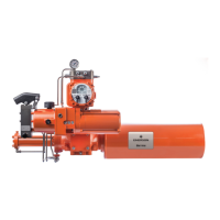
Item numbers correspond to attached schematic drawing 11794-S
(W) Bettis G-series Double Acting Actuator
(Z) Electric Motor
(Y) Hydraulic Pump
(I) Fluid Reservoir
(K) 3-Way Normally Closed Solenoid Valve for closing the actuator
(J) 3-Way Normally Closed Solenoid Valve for opening the actuator
(V) Adjustable Flow Controls. There are two flow controls located upstream of the
open and close solenoid valve items (J) & (K).
(AA) Suction Strainer
(T) Check Valve
(U) Relief Valve: A pressure relief valve is provided to protect the actuator and con-
trol system from over-pressurization caused by the pump or thermal expansion of the
hydraulic fluid.
(Q) Hydraulic Pressure Gauge
(R) Pressure Switch
(L) Hand Pump: Used to manually stroke the actuator open or closed.
(M) Hand Pump Selection Valves: These two valves are engaged to isolate the control
system before using the hand pump. Note: Both selection valves are engaged at the
same time when the hand pump is used to open or close the actuator.
(X) Shuttle Valve; (Optional) Used with an optional pressure transmitter.
(S) Pressure Transmitter(Optional)