8
Application Engineering
BULLETIN
AE4-1383 R5
© 2012 Emerson Climate Technologies, Inc.
Printed in the U.S.A.
CAUTION
Use an Ohmmeter with a maximum of 9 VDC for
checking – do not attempt to check continuity
through the sensors with any other type of
instrument. Any external voltage or current
may cause damage requiring compressor
replacement.
a) During normal operation, this resistance value
should read less than 4500 ohms ±20%.
b) If the M1-M2 contacts are open, the measured
S1-S2 value is above 2750 ohms ±20% and
the compressor has been tripped less then 30
minutes then the module is functioning properly.
• If the S1-S2 wire leads read less than 2750 ohms
±20% and the M1-M2 contacts are open, reset
the module by removing the power to T1-T2 for a
minimum of 5 seconds.
• Replace all wire leads and use a voltmeter to verify
the M1-M2 contacts are closed.
• If the M1-M2 contacts remain open and S1-S2 are
less than 2500 ohms, remove leads from the M1-
M2 contacts and jumper together, using a 100 ohm
resistor.
CAUTION
Compressor should start at this time. HOWEVER
DO NOT LEAVE JUMPER IN PLACE FOR
NORMAL SYSTEM OPERATIONS. THE JUMPER
IS USED FOR DIAGNOSTIC PURPOSES ONLY.
• Go to Compressor Supply Voltage Troubleshooting.
Compressor Voltage Supply Troubleshooting
• Remove phase sensing leads from the module from
L1/L2/L3.
• Use a voltmeter to measure the incoming 3 phase
voltage on L1/L2/L3. WARNING: L1/L2/L3 could
be at a potential up to 600VAC.
• Ensure proper voltage on each phase.
• Remove power to the module for a minimum of 5
seconds to reset and replace all wire leads. Re-
energize the module. If the M1-M2 contacts are open
with proper voltage to T1-T2, L1/L2/L3 and proper
resistance to S1-S2 then the module is faulty and
should be replaced.
Oil Management for Rack Applications
Copeland K5 refrigeration scrolls may be used on
multiple compressor parallel rack applications. This
requires the use of an oil management system to
maintain proper oil level in each compressor crankcase.
The sight glass connection supplied can accommodate
the mounting of the oil control devices.
Unlike semi-hermetic compressors, scrolls do not have
an oil pump with accompanying oil pressure safety
controls. Therefore, an external oil level control is
required.
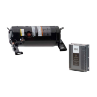
The OMB Oil Level Management Control combines
the functions of level control and timed compressor
shut-off should the level not come back to normal
within a set period of time. This device has been found
to provide excellent performance in fi eld tests on
scroll compressors and is recommended for parallel
system applications. Refer to Table 5 for Oil Monitoring
accessory part numbers.
Immediately after system start-up the oil reservoir
level will fl uctuate until equilibrium is reached. It is
advisable to monitor the oil level during this time to
assure suffi cient oil is available. This will prevent
unnecessary trips of the oil control system. Additional
information on oil management in Copeland Scroll
compressors can be found in Application Engineering
bulletin AE17-1320.
Discharge Mufflers
Gas fl ow through scroll compressors is continuous with
relatively low pulsation. External muffl ers applied to
piston compressors may not be required on Copeland
Scroll compressors. Due to system variability individual
tests should be conducted by the system manufacturer
to verify acceptable levels of sound and vibration.
Compressor Mounting
Compressor mounting must be selected based on
application. Consideration must be given to sound
reduction and tubing reliability. Some tubing geometry
or “shock loops” may be required to reduce vibration
transferred from the compressor to external tubing.
Mounting kit part numbers are listed in Table 4 at the
end of this bulletin.
Mounting for Rack Systems – Specially designed
steel spacers and rubber isolator pads are available
for Copeland Scroll 8 -15 HP rack applications. This
mounting arrangement limits the compressors motion
thereby minimizing potential problems of excessive
tubing stress. Suffi cient isolation is provided to prevent
vibration from being transmitted to the mounting
structure. This mounting arrangement is recommended
for multiple compressor rack installations. See Figure
7A for a detail of this mounting system.
 Loading...
