Quick Installation Guide
P/N MHM-97409.4
April 2010
CSI 9420
6
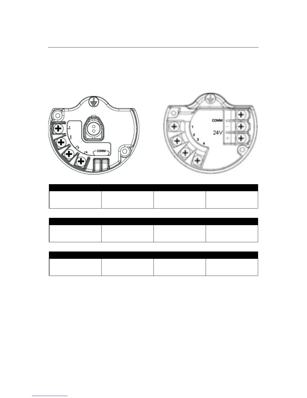
Connecting Sensors
One or two accelerometers can be connected to the CSI 9420. Only one accelerometer with
an embedded temperature sensor can be connected to the CSI 9420. Refer to Figure 3
showing the connector labels mentioned below.
Figure 3. CSI 9420 Terminal Diagram (battery powered version and externally powered version)
Table 1. Connecting One Accelerometer to the CSI 9420
Table 2. Connecting Two Accelerometers to the CSI 9420
Table 3. Connecting One Sensor with Vibration and Temperature
Connecting One Accelerometer
Connector labeled 1:
Sensor Power
(Red Wire)
Connector labeled 2:
Sensor Signal
(White Wire)
Connector labeled 3:
Unused
Connector labeled 4:
Sensor Common
(Black Wire)
Connecting Two Accelerometers
Connector labeled 1:
Power - Both Sensors
(Two Red Wires)
Connector labeled 2:
Signal - Sensor 1
(White Wire)
Connector labeled 3:
Signal - Sensor 2
(White Wire)
Connector labeled 4:
Sensor Commons
(Two Black Wires)
Connecting One Sensor with Vibration and Temperature
Connector labeled 1:
Sensore Power
(Red Wire)
Connector labeled 2:
Vibration Signal
(White Wire)
Connector labeled 3:
Temperature Signal
(Green Wire)
Connector labeled 4:
Sensor Common
(Black wire)

 Loading...