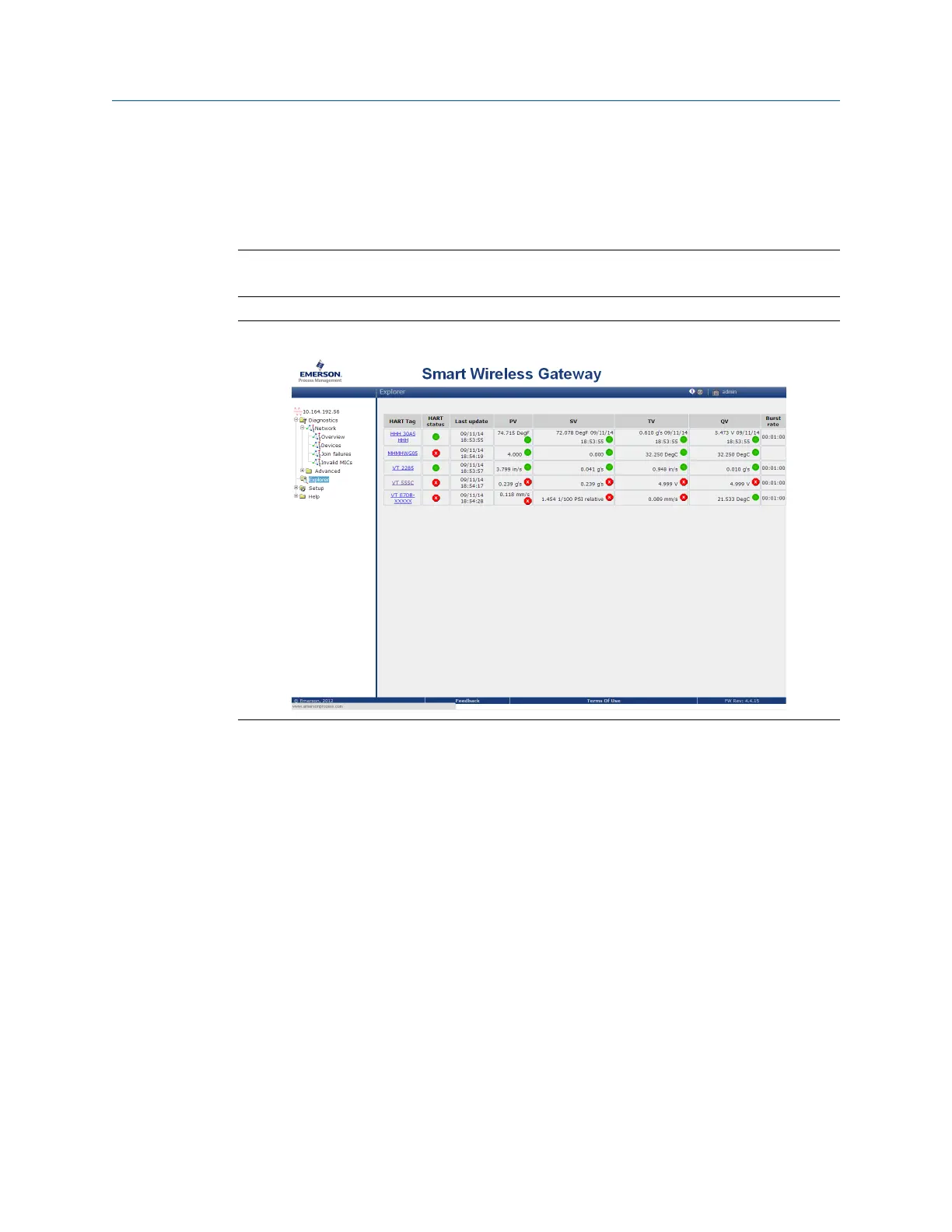
The Explorer page displays the transmitter tag name, PV, SV, TV, QV, time of last update,
and update rate (burst rate). A green status indicator means that the device is working
properly. A red indicator means there is a problem with either the device or its
communication path.
Note
It is normal for the CSI 9420 to have a red “X” on the screen until the sensor is installed.
Smart Wireless GatewayFigure 4-1:
Click on a tag name to display more information about the device.
If the CSI 9420 is configured with the Network ID and Join Key, and sufficient time for
network polling has passed, the transmitter will then be connected to the network.
The most common cause of incorrect operation is that the Network ID or Join Key are not
set correctly in the device. The Network ID and Join Key in the device must match those
found on the Smart Wireless Gateway. From the Smart Wireless Gateway, click Setup >
Network > Settings to display the Network ID and Join Key. Make sure the setting for "Show
join key" is set to Yes.
Operation and maintenance
MHM-97408, Rev 15 89

 Loading...