Document Part # 026-4283 Rev 0 Page 6 of 8
©2022 Emerson Digital Cold Chain, Inc. This document may be photocopied for personal use.
Visit our website at www.climate.emerson.com for the latest technical documentation and updates.
6 Serial Line - CanBus
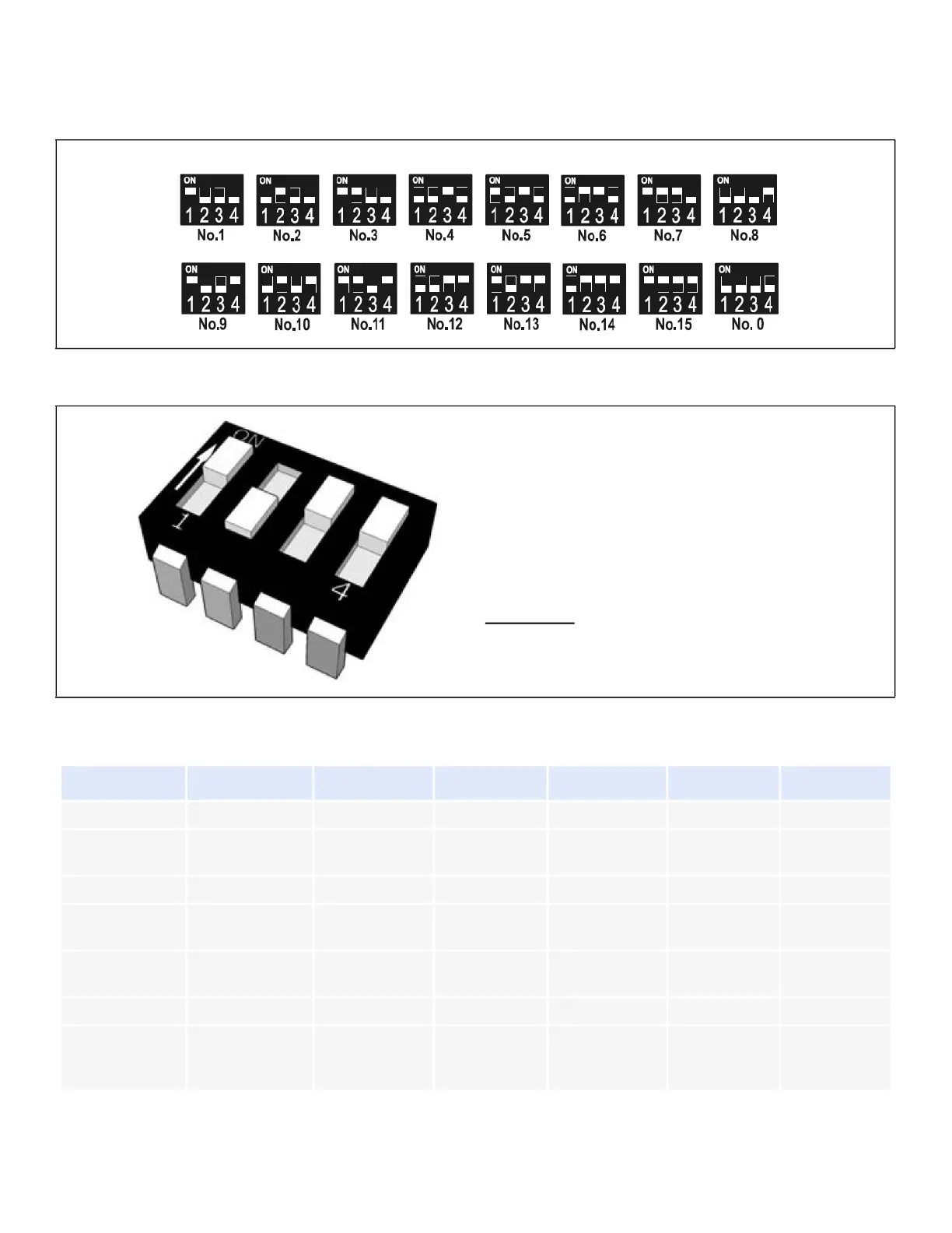
The device can communicate through CanBus serial line only when a correct address is set. The addressing is made
through the dip-switch called Address as you can see in the following drawing:
The following table has to be used to configure ISaGRAF lines to connect the valve actuator.
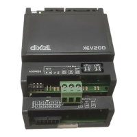
Figure 6-1 - CanBus Serial Line
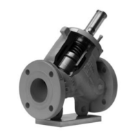
Figure 6-2 - CanBus Device
LINE GEN_LINE
GEN_AO GEN_AO GEN_AO GEN_A1 GEN_DI
channel number
4 2 7 4 3
line_num
CanBus
Number
CanBus
Number
CanBus
Number
CanBus
Number
CanBus
Number
CanBus
Number
name CAN
par_1
CanBus
Number
CanBus
Number
CanBus
Number
CanBus
Number
CanBus
Number
CanBus
Number
par_2
CAN node
address
16 17 26 1 31
par_3 10
I/O 1
EVV_StepsOutp
ut Valve 1
EEV_OutRateV
alve 1
EVV_ProbeTCo
nfiguration
Valve 1
EVV_Temperat
ure Valve 1
EVV_ValvePosi
tion Valve 1
The address is set in binary mode.
Every selector has a different weight, in figure
nearby the address is:
1 x 1 = 1
2 x 0 = 0
4 x 1 = 4
8 x 1 = 8
1+4+8=13
 Loading...