Document Part # 026-4283 Rev 0 Page 7 of 8
©2022 Emerson Digital Cold Chain, Inc. This document may be photocopied for personal use.
Visit our website at www.climate.emerson.com for the latest technical documentation and updates.
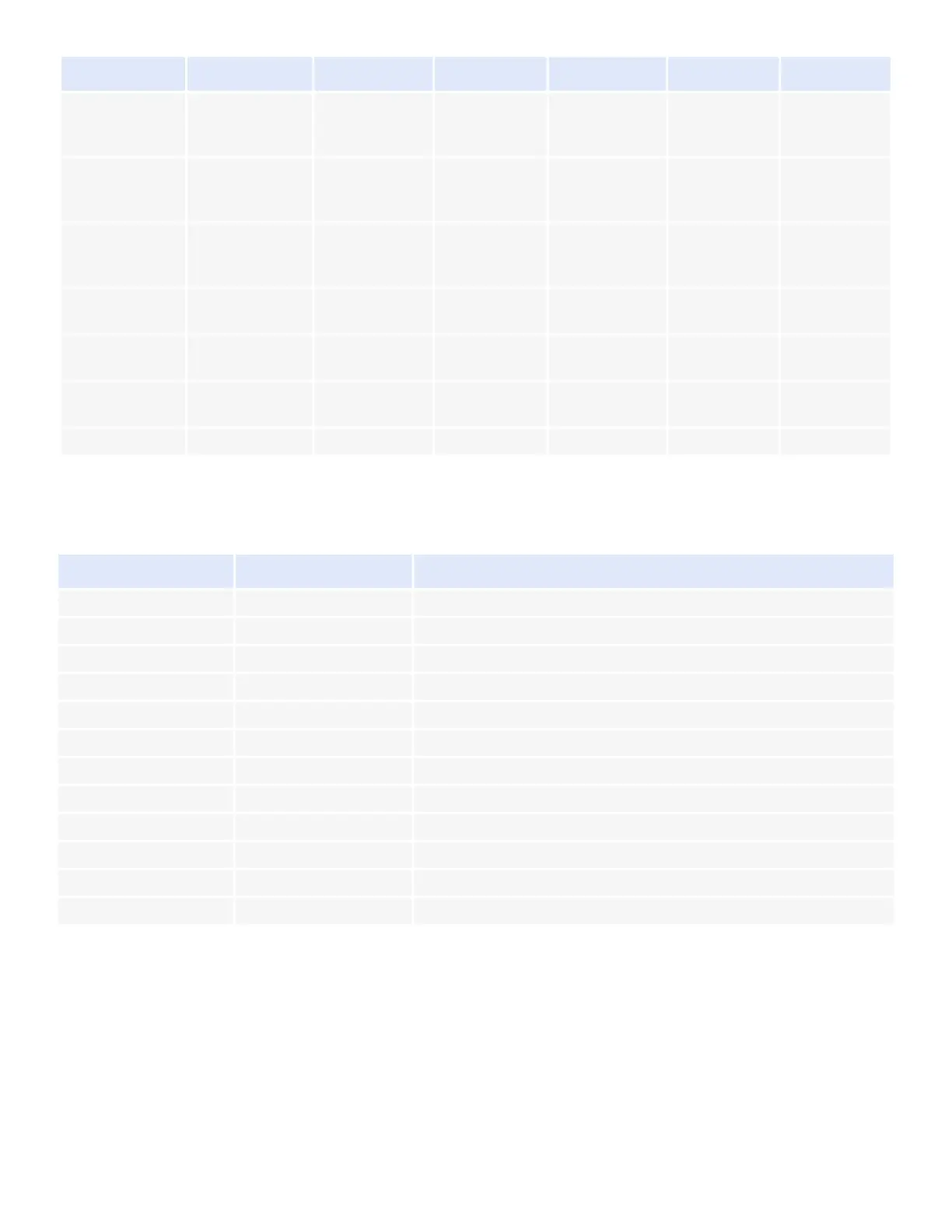
7 LEDs Meaning
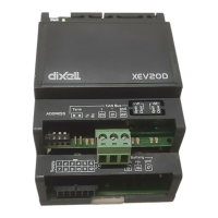
The following table has to be used to configure ISaGRAF lines to connect the valve actuator.
I/O 2
EVV_StepsOutp
ut Valve 2
EEV_OutRateV
alve 2
EVV_ProbeTCo
nfiguration
Valve 2
EVV_Temperat
ure Valve 2
EVV_Valve
Posi
tion Valve 2
I/O 3
EVV_Steps
MaxValve 1
EVV_ProbePCo
nfiguration
Valve 1
EVV_Pressure
Valve 1
I/O 4
EVV_Steps
MaxValve 2
EVV_ProbePCo
nfiguration
Valve 2
EVV_Pressure
Valve 2
I/O 5
EVV_OutPhasC
urrent Valve 1
I/O 6
EVV_OutPhasC
urrent Valve 2
I/O 7
EVV_OutValveC
onfiguration
I/O 8
LED MODE
MEANING
PWR ON On The device is correctly powered
ALARM On An alarm is present
TX/RX Blinking CanBus or LAN activity, communication activated
TX/RX On No link
OPEN V1 Blinking Valve 1 is opening
OPEN V1 On Valve 1 completely opened
CLOSE V1 Blinking Valve 1 is closing
CLOSE V1 On Valve 1 completely closed
OPEN V2 Blinking Valve 2 is opening
OPEN V2 On Valve 2 completely opened
CLOSE V2 Blinking Valve 2 is closing
CLOSE V2 On Valve 2 completely closed
LINE GEN_LINE
GEN_AO GEN_AO GEN_AO GEN_A1 GEN_DI
 Loading...