Chapter 4 Operation Instructions 39
EV2000 Series Universal Variable Speed Drive User Manual
UNI T
HZ
r/min
A
V
%
PARAMETER
.
补偿前频率
普通运行 正
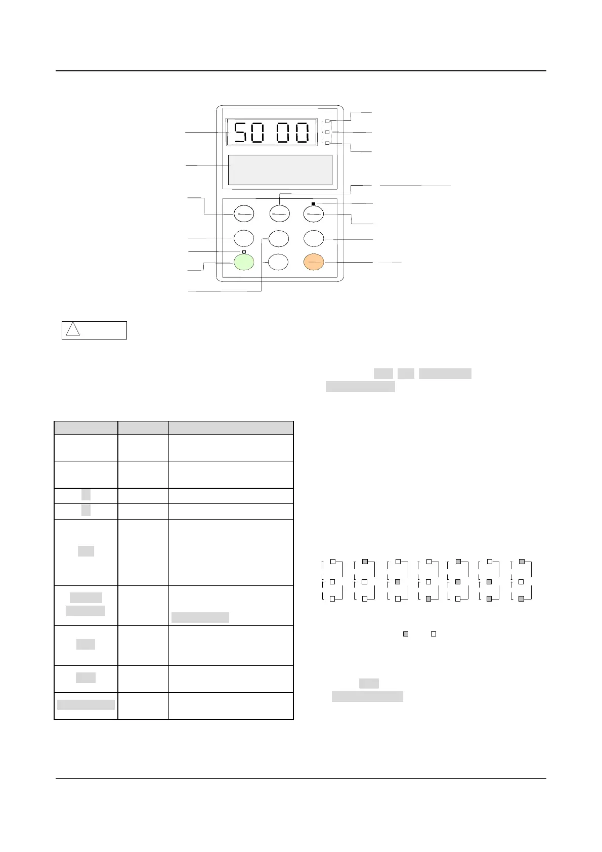
4-bit LED
Current unit:A
Voltage unit:V
Data input
Control mode indicator
Jog
Stop
Reset
Rotating speed:r/min
Line speed:m/s
ENTER
DATA
PANEL
REMOTE
RUN
JOG
STOP
RESET
MENU
ESC
UNI T
HZ
r/min
A
V
%
PARAMETER
.
补偿前频率
普通运行 正
Frequency unit:Hz
ENTER
DATA
ENTER
DATA
PANEL
REMOTE
PANEL
REMOTE
RUNRUN
STOP
RESET
STOP
RESET
MENU
ESC
MENU
ESC
UNI T
HZ
r/min
A
V
%
PARAMETER
.
补偿前频率
普通运行 正
Enter
ENTER
DATA
ENTER
DATA
PANEL
REMOTE
PANEL
REMOTE
RUNRUN
STOP
RESET
STOP
RESET
MENU
ESC
MENU
ESC
UNI T
HZ
r/min
A
V
m/s
%
PARAMETER
.
Freq. before compensation
RUN FWD
Control mode selecting key
ENTER
DATA
ENTER
DATA
PANEL
REMOTE
PANEL
REMOTE
▲
RUN
RUN
STOP
RESET
STOP
RESET
MENU
ESC
MENU
ESC
MENU
ESC
MENU
ESC
LCD display
Program
Move
Running Indicator
Run
Increase/Decrease
▲
▲
▲
Fig. 4-2 Illustration of operation panel
Attention
!
Operation panel of EV2000 is not compatible with the panel of other Emerson variable speed drives.
4.2.2 Function of Keys
There are 9 keys on the operation panel of the drive and
the functions of each key is shown in Table 4-1.
Table 4-1 Function of operation panel
Key Name Function
MENU/ESC
Program/
exit
Enter or exit programming
status
ENTER/DATA
Function/
data
Enter lower level menu or
confirm data
▲
Increase
Increase data or parameter
▼
Decrease
Decrease data or parameter
XX Shift
In editing status, pressing
this key select the Bit to be
modified. In other status, this
key is used to scroll through
the parameters.
PANEL/
REMOTE
Control
mode
selection
When a control mode is
selected, press
ENTER/DATA to enter
JOG Jog key
In panel control mode, press
this key to start Jog
operation.
RUN Run key
In panel control mode, press
this key to run the drive.
STOP/RESET Stop/reset
Press this key to stop or
reset the drive.
Notes:
Functions of RUN, JOG, STOP/RESET and
PANEL/REMOTE are also limited by F9.07.
4.2.3 Function Descriptions of LED and Indicators
The operation panel consists of a 4-digit seven
segments display, 3 LED indicators that indicate unit
and 2 status indicators as shown in Fig. 4-3. The seven
segments can display the status parameters,
parameters and fault codes of the drive. These 3 unit
indicators have 7 different combinations and each
combination corresponds to one type of unit. The
relationship between the combination of the indicators
and the unit is shown in Fig. 4-3:
%
r/min
m/s
%
A
V
Hz
UNIT
Hz
r/min
m/s
%
A
V
Hz
UNIT
A
r/min
m/s
A
V
Hz
UNIT
V
r/min
m/s
%
A
V
Hz
UNIT
r/min
r/min
m/s
%
A
V
Hz
UNIT
m/s
r/min
m/s
%
A
V
Hz
UNIT
%
r/min
m/s
%
A
V
Hz
UNIT
No
unit
On
Off
Fig. 4-3 Unit represented by combination of the indicators
Two status indicators: Operating status indicator is
above the RUN key. The control mode indicator is above
the PANEL/REMOTE key, and the functions of these
indicators are shown in Table 4-2.
 Loading...


