Instruction Manual
D103785X012
Maintenance and Troubleshooting
June 2017
65
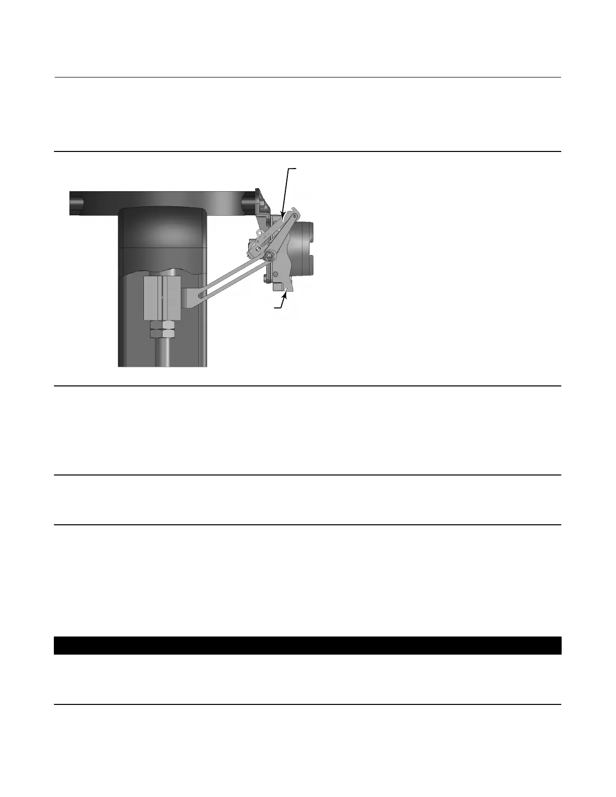
1. For sliding‐stem applications only, a protective shield for the feedback linkage is attached to the side of the module
base assembly as shown in figure 6‐1. Remove this shield and keep for reuse on the replacement module. The
replacement module will not have this protective shield.
Figure 6‐1. Protective Shield for Feedback Linkage
SHIELD
FEEDBACK ARM EXTENSION,
BIAS SPRING
X0908
2. Unscrew the four captive screws in the cover (key 43) and remove the cover from the module base (key 2).
3. Using a 6 mm hex socket wrench, loosen the three‐socket head screws (key 38). These screws are captive in the
module base by retaining rings (key 154).
Note
The module base is linked to the housing by two cable assemblies. Disconnect these cable assemblies after you pull the module
base out of the housing.
4. Pull the module base straight out of the housing (key 1). Once clear of the housing, swing the module base to the
side of the housing to gain access to the cable assemblies.
5. The base unit has two cable assemblies, shown in figure 6‐2, which connect the module base, via the printed wiring
board assembly, to the travel sensor and the terminal box. Disconnect these cable assemblies from the printed
wiring board assembly on the back of the module base.
CAUTION
To avoid affecting performance of the instrument, take care not to damage the module base seal or guide surface. Do not
bump or damage the bare connector pins on the PWB assembly. Damaging either the module base or guide surface may
result in material damage, which could compromise the instruments ability to maintain a pressure seal.

 Loading...


