Instruction Manual
D103785X012
Maintenance and Troubleshooting
June 2017
68
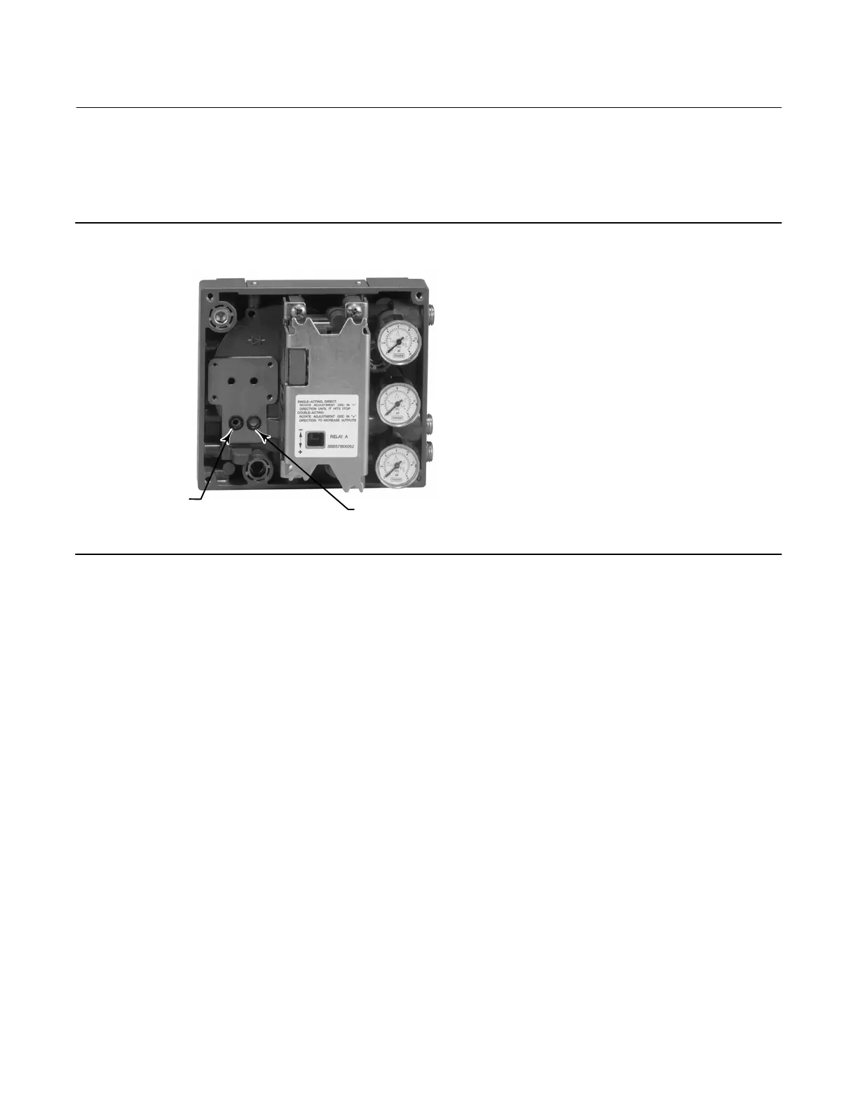
3. Install a new screen in the supply port as shown in figure 6‐3.
4. Inspect the O‐ring (key 39) in the I/P output port; if necessary, replace it.
5. Reinstall the I/P converter (key 41) and shroud (key 169) as described in the Replacing the I/P Converter procedure.
Figure 6‐3. I/P Filter Location
SCREEN (FILTER) LOCATED IN I/P
CONVERTER SUPPLY PORT
O‐RING LOCATED
IN I/P CONVERTER
OUTPUT PORT
W8072
Removing the I/P Converter
1. Remove the front cover (key 43), if not already removed.
2. Refer to figure 6‐4. Using a 2.5 mm hex socket wrench, remove the four socket‐head screws (key 23) that attach the
shroud (key 169) and I/P converter (key 41) to the module base (key 2).
3. Remove the shroud (key 169); then pull the I/P converter (key 41) straight out of the module base (key 2). Be
careful not to damage the two electrical leads that come out of the base of the I/P converter.
4. Ensure that the O‐ring (key 39) and screen (key 231) stay in the module base and do not come out with the I/P
converter (key 41).
Replacing the I/P Converter
1. Refer to figure 6‐3. Inspect the condition of the O‐ring (key 39) and screen (key 231) in the module base (key 2).
Replace them, if necessary. Apply silicone lubricant to the O‐rings.
2. Ensure the two boots (key 210) shown in figure 6‐4 are properly installed on the electrical leads.
3. Install the I/P converter (key 41) straight into the module base (key 2), taking care that the two electrical leads feed
into the guides in the module base. These guides route the leads to the printed wiring board assembly submodule.
4. Install the shroud (key 169) over the I/P converter (key 41).
5. Install the four socket‐head screws (key 23) and evenly tighten them in a crisscross pattern to a final torque of
1.6 NSm (14 lbfSin).
6. After replacing the I/P converter, calibrate travel or perform touch‐up calibration to maintain accuracy
specifications.

 Loading...


