Instruction Manual
D103785X012
Maintenance and Troubleshooting
June 2017
70
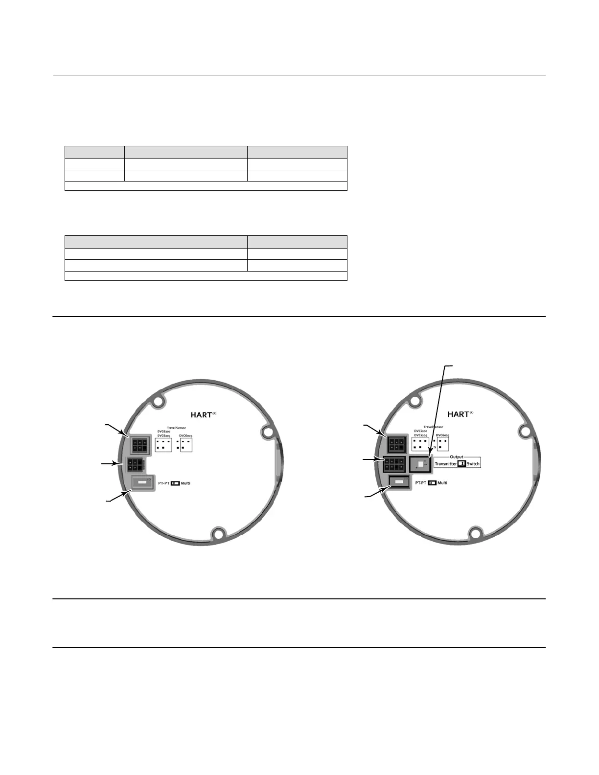
5. Set the DIP switch on the PWB assembly according to table 6‐2. On units that have the optional 4-20 mA position
transmitter or switch hardware installed, set the Transmitter or Switch option according to table 6‐3.
Table 6‐2. DIP Switch Configuration
(1)
Switch Label Operational Mode DIP Switch Position
PT-PT 420 mA PointtoPoint Loop LEFT
Multi 24 VDC MultiDrop Loop RIGHT
1. Refer to figure 6‐5 for switch location.
Table 6‐3. Output Switch Configuration
(1)
Switch Label/Function DIP Switch Position
Transmitter LEFT
Switch RIGHT
1. Refer to figure 6‐5 for switch location.
X0432
Figure 6‐5. Printed Wiring Board (PWB) Connections and Settings
TRANSMITTER/SWITCH
SELECTION
TRAVEL SENSOR
CONNECTOR
TERMINAL BOX
CONNECTOR
OPERATIONAL
MODE SELECTION
TRAVEL SENSOR
CONNECTOR
TERMINAL BOX
CONNECTOR
OPERATIONAL
MODE SELECTION
X0463
Note
For the digital valve controller to operate with a 4 to 20 mA control signal, be sure the DIP switch is in the point‐to‐point loop
position.
6. Reassemble the module base to the housing by performing the Replacing the Module Base procedure.
7. Setup and calibrate the DVC6005 HW2 base unit.

 Loading...


