EasyManua.ls Logo

Emerson Fisher FIELDVUE DVC6000 User Manual

Emerson Fisher FIELDVUE DVC6000
162 pages
To Next Page IconTo Next Page
To Previous Page IconTo Previous Page
Page #5 background image
DVC6000 Digital Valve Controllers
ii
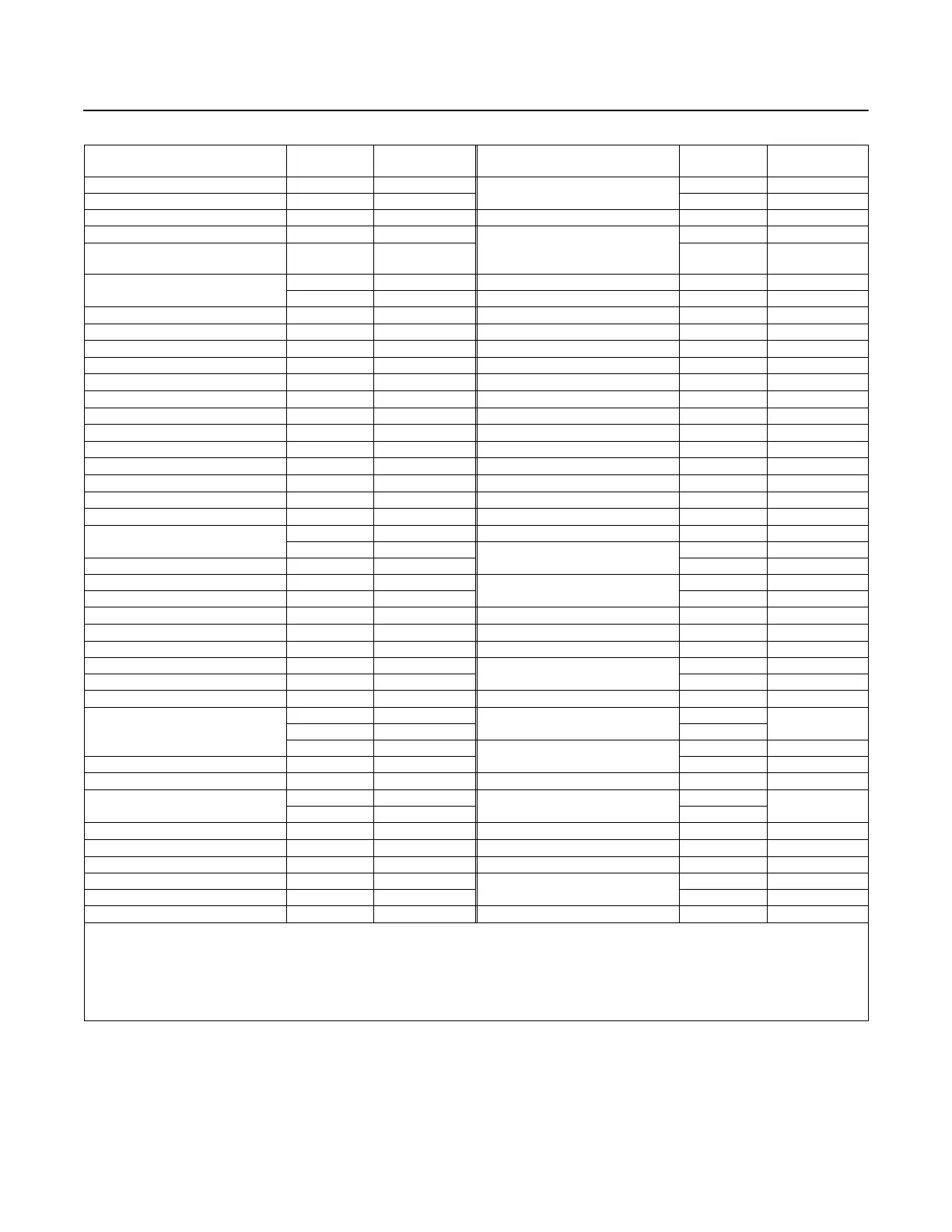
Fast Key Sequence for Instrument Level HC, AD, PD, and ODV
Function/Variable
Fast-Key
Sequence
Coordinates
(1)
Function/Variable
Fast-Key
Sequence
Coordinates
(1)
Partial Stroke Test
(3)
2-5 2-F
Travel
3-3 2-G
Partial Stroke Test Enable
(3)
1-2-7-1 3-D 1-2-3-4-1 9-E
Partial Stroke Test Pressure Limit
(3)
1-2-3-6-1 10-G Travel / Pressure Select 1-2-2-2-1 6-C
Partial Stroke Test Start Point
(3)
1-2-2-2-4-2 8-D
Travel Accumulatorv
3-6-6 4-H
Partial Stroke Test Variables
View/Edit
(3)
1-2-7-2 3-D 1-2-3-5-3-2 12-H
Performance Tuner
(2)
1-1-2 2-B Travel Accumulator Alert Enable 1-2-3-5-3-1 12-H
1-2-2-1-1-5 8-A Travel Accumulator Alert Point 1-2-3-5-3-3 12-I
Polling Address 1-2-5-1-7 6-G Travel Alert Dead Band 1-2-3-4-3 9-E
Pressure A 3-5-1 4-G Travel Alert Hi Enable 1-2-3-4-6-1 10-F
Pressure B 3-5-2 4-G Travel Alert Hi Hi Enable 1-2-3-4-5-1 12-E
Pressure Control Active Enable 1-2-4-3-1 8-H Travel Alert Hi Hi Point 1-2-3-4-5-3 12-F
Pressure Deviation Alert Enable
(3)
1-2-3-6-2 10-G Travel Alert Hi Point 1-2-3-4-6-3 10-F
Pressure Deviation Alert Point
(3)
1-2-3-6-3 10-G Travel Alert Lo Enable 1-2-3-4-6-2 10-F
Pressure Deviation Time
(3)
1-2-3-6-4 10-G Travel Alert Lo Lo Enable 1-2-3-4-5-2 12-E
Pressure Range Hi 1-2-2-2-3-1 10-D Travel Alert Lo Lo Point 1-2-3-4-5-4 12-F
Pressure Range Lo 1-2-2-2-3-2 10-D Travel Alert Lo Point 1-2-3-4-6-4 10-F
Pressure Sensor Shutdown
(2)
1-2-3-2-3 12-D Travel Deviation Alert Enable 1-2-3-4-4-1 10-E
Pressure Sensors—Calibration 1-3-2-1 4-E Travel Deviation Alert Point 1-2-3-4-4-2 10-E
Pressure Tuning Set 1-2-2-1-3-1 8-B Travel Deviation Time 1-2-3-4-4-3 10-E
Pressure Units 1-2-5-2-1 6-G Travel Limit / Cutoff Hi Enable 1-2-3-4-7-1 12-F
Protection
Hot Key-3 1-A Travel Limit / Cutoff Lo Enable 1-2-3-4-7-2 12-F
1-2-1-5 4-B
Travel Limit Hi
1-2-3-4-7-6 12-G
Raw Travel Input 3-6-7 4-H 1-2-2-2-2-4 10-C
Reference Voltage Shutdown 1-2-3-1-3-7 12-C
Travel Limit Lo
1-2-3-4-7-7 12-G
Relay Adjust 1-3-3 3-E 1-2-2-2-2-5 10-C
Relay Type 1-2-5-4 4-F Travel Sensor Adjust 1322 4E
Restart Control Mode 1-2-1-3 4-B Travel Sensor Motion 1-2-6-5 3-E
Restore Factory Settings 1-3-4 3-E Travel Sensor Shutdown 1-2-3-2-1 12-C
Set Point Rate Close 1-2-2-5-2 5-D
Travel Setpoint
1-2-3-4-2 9-E
Set Point Rate Open 1-2-2-5-1 5-D 3-2 2-G
Setup Wizard 1-1-1 2-B Travel Tuning Set 1-2-2-1-1-1 8-A
Stabilize/Optimize
Hot Key-4 1-A
Valve Group Enable
1-2-3-6-5-2
10-H
1-1-2
(4)
2-B 1-2-3-7-5-2
1-2-2-1-1-4 8-A
Valve Serial Number
1-2-5-1-5 6-F
Status 2-2 2-F 1-2-6-2 3-D
Stroke Valve 2-4 2-F Valve Style 1-2-6-3 3-D
Supply Pressure
(2)
3-5-4 4-G
View Alert Records
1-2-3-6-3
10-H
1-2-3-3-2-2 12-E 1-2-3-7-3
Supply Pressure Lo Alert Enable
(5)
1-2-3-3-2-1 12-E View/Edit Feedback Connection 1-2-6-6 3-E
Supply Pressure Lo Alert Point
(5)
1-2-3-3-2-3 12-E View/Edit Lag Time
(5)
1-2-2-5-3 5-D
Temperature 3-6-2 4-H View/Edit Lead/Lag
(3)
1-2-2-5-3 5-D
Temperature Sensor Shutdown 1-2-3-2-2 12-D
View Number of Days Powered Up
2-3-3 3-F
Temperature Units 1-2-5-2-2 6-G 3-6-8 4-H
Zero Power Condition 1-2-5-5 4-G
NOTE: Italicized Fast-Key Sequence indicates fast-key sequence is applicable only for instrument level ODV.
1. Coordinates are to help locate the item on the menu tree on the following pages.
2. Not available in instrument level HC.
3. Instrument level ODV only.
4. Instrument level HC only.
5. Instrument level HC, AD, and PD only.6
7. Firmware 7 only.

Table of Contents

Question and Answer IconNeed help?

Do you have a question about the Emerson Fisher FIELDVUE DVC6000 and is the answer not in the manual?

Emerson Fisher FIELDVUE DVC6000 Specifications

General IconGeneral
ModelDVC6000
TypeDigital Valve Controller
ManufacturerEmerson
Operating Temperature-40 to 85°C (-40 to 185°F)
Communication ProtocolsHART
Power Supply24 VDC
Ingress ProtectionIP66
WeightApproximately 2.3 kg (5.1 lb)
Input Signal4-20 mA
CertificationsATEX, IECEx, CSA, FM
MountingDirectly to valve or pipe

Summary

Introduction and Specifications

Scope of Manual

Outlines manual's coverage: specs, installation, operation, maintenance for DVC6000 controllers.

Description

Explains DVC6000 as microprocessor-based instruments converting current to pneumatic output.

Specifications

Details configurations, input/output signals, and environmental conditions for the controller.

Installation

Hazardous Area Classifications and Special Instructions

Covers CSA, FM, ATEX, IECEx classifications and safe use instructions for hazardous locations.

Mounting Guidelines

Instructions for mounting DVC6000 units on various actuators, including DVC6010, DVC6020, DVC6030.

Pneumatic Connections

Covers supply, output connections, and actuator configurations for pneumatic systems.

Electrical Connections

Details 4-20 mA loop, communication, and wiring practices for electrical setup.

Basic Setup

Instrument Mode

Setting instrument mode to 'Out Of Service' or 'In Service' for calibration and setup.

Configuration Protection

Enabling/disabling protection, possibly requiring a jumper across auxiliary terminals.

Setup Wizard

Guides automatic setup using actuator data, controlling travel, units, and actuator specifics.

Using the Performance Tuner

Optimizing digital valve controller tuning for better response, especially for remote units.

Detailed Setup

Mode and Protection

Setting instrument mode, control mode (Analog/Digital/Test), restart mode, and protection.

Response Control

Configuring tuning sets, travel/pressure control, input characterization, and dynamic response.

Alert Setup

Configuring electronics, sensor, environment, travel, history, SIS, and alert record settings.

Calibration

Travel Calibration

Procedures for auto, manual, and touch-up calibration of valve travel for accurate positioning.

Sensor Calibration

Calibrating pressure sensors (output A/B, supply) and travel sensors for accurate readings.

Relay Adjust

Adjusting the pneumatic relay, particularly for double-acting relays, for correct valve positioning.

Restore Factory Settings

Resetting calibration settings for sensors and tuning sets to their factory defaults.

Viewing Device Variables and Diagnostics

Service Tools

Accessing alerts, status, device records, stroke valve, and partial stroke test functions.

Overview

Viewing instrument data like analog input, setpoint, travel, drive signal, pressure, and variables.

Device Information

Displaying HART tag, Device ID, manufacturer, model, revisions, instrument level, and DD info.

Maintenance and Troubleshooting

Module Base Maintenance

Procedures for module base removal/replacement, including I/P converter, PWB, and pneumatic relay.

Travel Sensor Maintenance

Steps for disassembling/reassembling travel sensors for DVC6000 and remote feedback units.

Troubleshooting

Checklist and guidance for diagnosing and resolving communication or output issues.

Replaceable Parts

Parts Ordering

Guidelines for ordering replacement parts, referencing serial and part numbers.

Parts Kits

Lists available spare parts kits like elastomer, hardware, conversion, and feedback units.

Parts List

Detailed component list with key numbers and part numbers, categorized by assembly.

Appendix A: Principle of Operation

HART Communication

Explains HART protocol for digital communication over 4-20 mA loop and multidropping.

DVC6000 Operation

Describes DVC6000 components and signal flow from input to pneumatic output.

Appendix B: Loop Schematics/Nameplates

CSA Loop Schematics and Nameplates

Provides CSA loop schematics and nameplates for DVC6010, DVC6020, DVC6030, and DVC6005.

FM Loop Schematics and Nameplates

Presents FM schematics and nameplates for DVC6010, DVC6020, DVC6030, DVC6005, DVC6015, DVC6025, DVC6035.

ATEX Loop Schematics and Nameplates

Details ATEX schematics and nameplates for flameproof and type n configurations.

IECEx Loop Schematics and Nameplates

Includes IECEx schematics and nameplates for various DVC6000 models and configurations.

Related product manuals