DVC6000f Digital Valve Controllers
December 2009
4-152
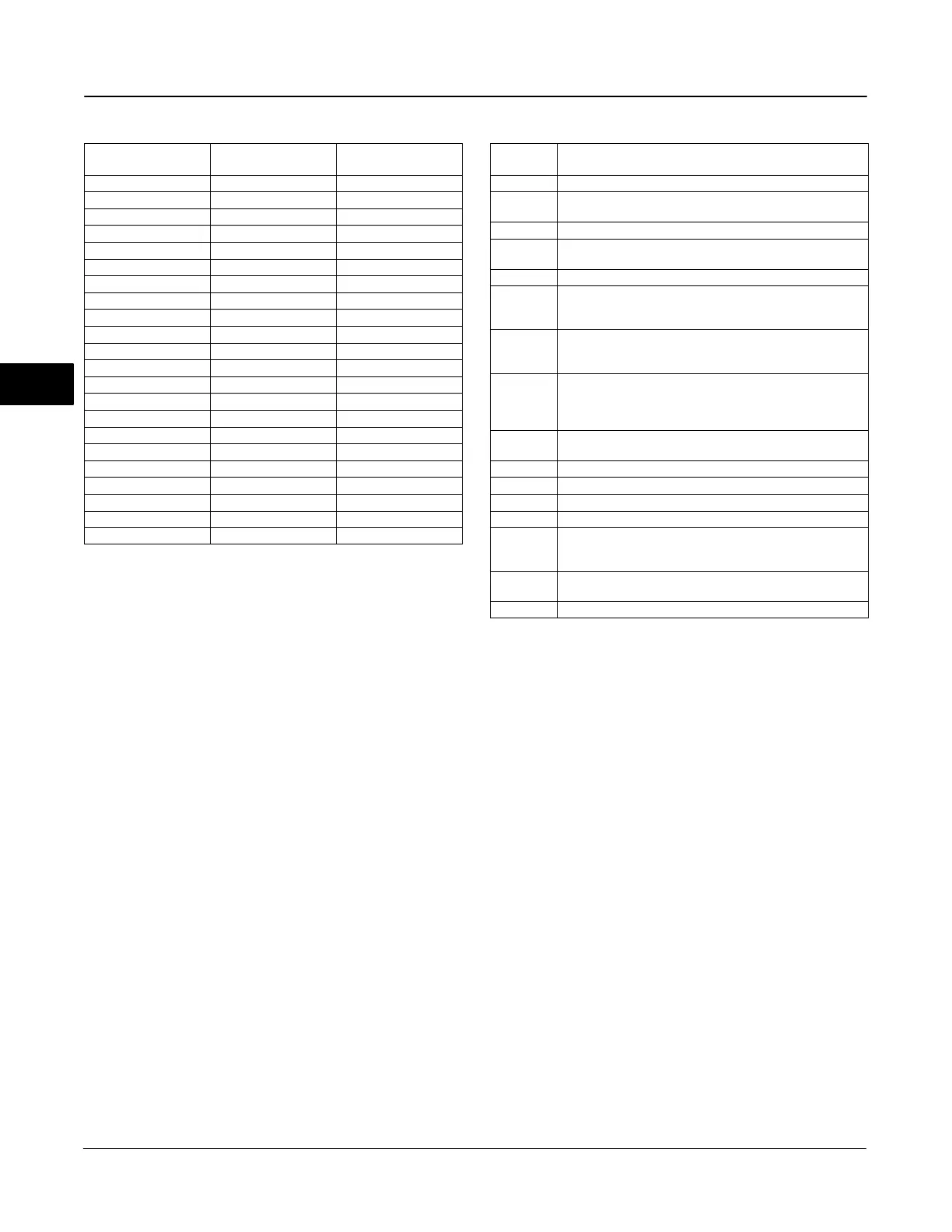
Table 4-69. Valve Set Point for Discrete State
Discrete State
Valve Set Point with
IO_OPTS Invert = 0
Valve Set Point with
IO_OPTS Invert = 1
0 Closed Open
1 Open Closed
5 5% Closed
10 10% Closed
15 15% Closed
20 20% Closed
25 25% Closed
30 30% Closed
35 35% Closed
40 40% Closed
45 45% Closed
50 50% Closed
55 55% Closed
60 60% Closed
65 65% Closed
70 70% Closed
75 75% Closed
80 80% Closed
85 85% Closed
90 90% Closed
95 95% Closed
100 Open Closed
(PV_D [7]), and a manually-entered SP_D [8] value is
overwritten on the block’s next execution cycle. This
option can prevent a state change when transitioning
from Manual to Automatic mode. You can disable this
option in Manual or Out of Service mode only.
The Invert option inverts the set point at SP_D [8]
before it is stored in OUT_D [9]. With this option
enabled, OUT_D [9] becomes an inverted copy of
SP_D [8] where non-zero values of SP_D [8] are
considered a logic 1. With this option disabled, OUT_D
[9] is a direct copy of SP_D [8]. The readback value is
processed through the Invert option to become PV_D
[7]. The Use PV for BKCAL_OUT option specifies that
BKCAL _OUT equal the value of the process variable
(PV_D [7]) instead of the set point (SP_D [8]). If you
do not enable this option, BKCAL_OUT will equal
SP_D [8].
Output Block PV Status
The Output Block PV Status is determined by the
value of the PlantWeb Alerts Set PV Status parameter
in the transducer block (PWA_SET_STATUS [97]),
the Transducer Block mode, and enabled Active
PlantWeb alarms. Refer to table 4-10.
Table 4-70. BLOCK_ERR Conditions
Condition
Number
Condition Name and Description
0 Other (N/A)
1
Block Configuration Error - SHED_OPT or CHANNEL set to
0 (uninitialized)
2 Link Configuration Error (N/A)
3
Simulate active - Simulation is enabled and the block is using
a simulated value in its execution.
4 Local Override - Device in fault state. Actual mode LO.
5
Device Fault State Set - DO block in fault state after
FSTATE_TIME because of Bad status or IFS substatus on
CAS_IN_D or Resource block commanded fault state.
6
Device Needs Maintenance Soon - Indicates a Maintenance
PlantWeb Alert condition is active if Block Error Reporting is
enabled. See page 4-40.
7
Input failure/process variable has Bad status - PV has bad
status and Feature Select in the Resource block has the Out
Readback bit set or the transducer block mode is Out of
Service.
8
Output failure - PV has bad status or the transducer block
mode is Out of Service.
9 Memory Failure (N/A)
10 Lost Static Data (N/A)
11 Lost NV Data (N/A)
12 Readback Check Failed (N/A)
13
Device Needs Maintenance Now - Indicates Failed
PlantWeb Alert condition is active if Block Error Reporting is
enabled. See page 4-40.
14
Power Up - This condition exists after power up until actual
mode is not Out of Service.
15 Out of Service - The block is in Out of Service (OOS) mode.
Block Errors
Table 4-70 lists conditions reported in the
BLOCK_ERR [6] parameter. Conditions in italics are
not applicable for the DO block and are provided only
for your reference.
Action on Fault Detection
Fault State is caused by one of three sources: A
status pertaining to CAS, A status pertaining to RCAS,
or SET_FSTATE [29] in the resource block. To
implement Fault State, configure the following
parameters:
IO_OPTS [14]: Determines the action OUT_D [9] will
take upon a fault state. If the IO_OPTS [14] “Fault
State to Value” is not selected, then OUT_D [9] holds
its last position when Fault State is set. If “Fault State
to Value” is selected, OUT_D [9] goes to the
FSTATE_VAL_D [20] value when Fault State is set.
FSTATE_TIME [19]: The length of time, in seconds,
that the DO block will wait to set Fault State. When
4

 Loading...


