Maintenance and Troubleshooting
December 2009
7-7
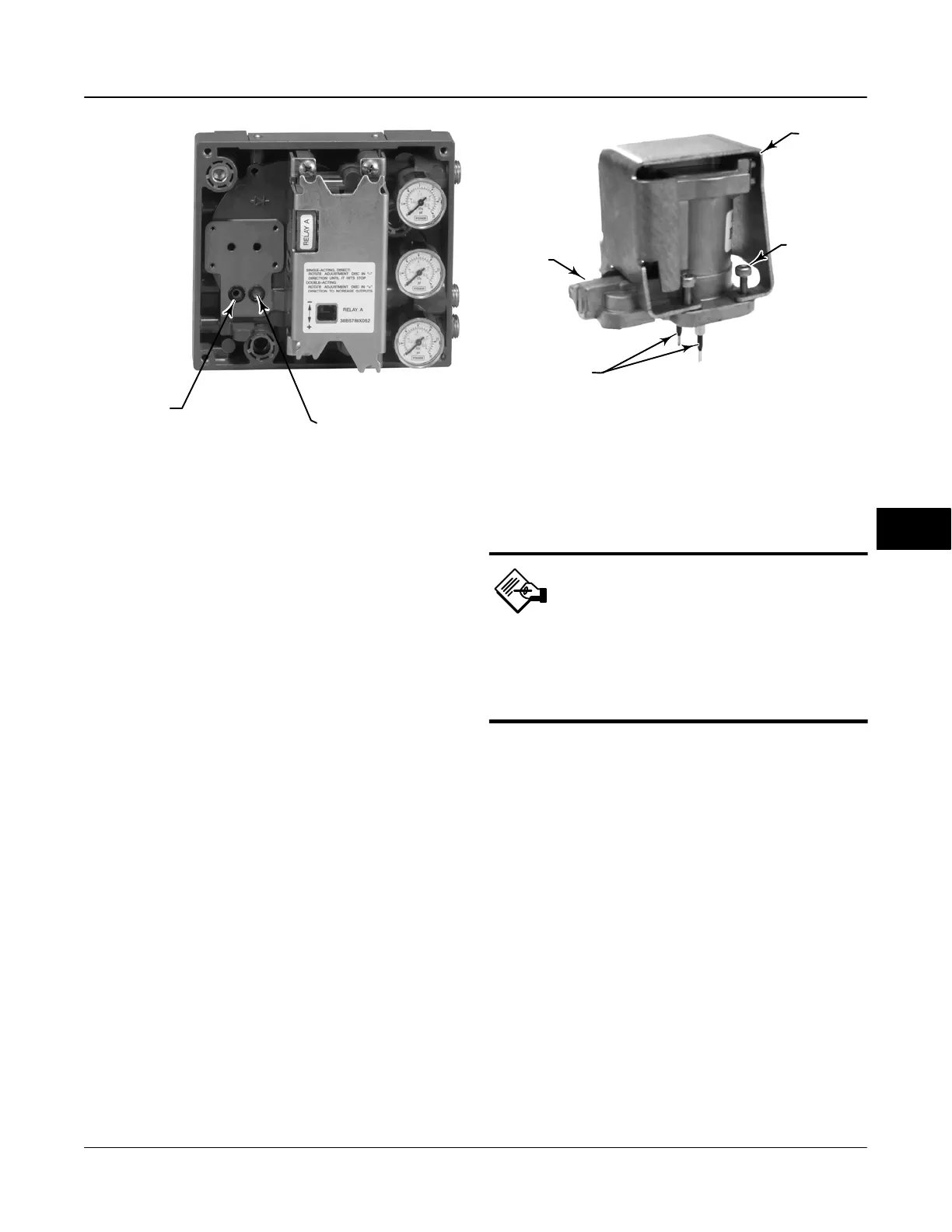
Figure 7-3. I/P Filter Location
O-RING LOCATED
IN I/P CONVERTER
OUTPUT PORT
W8072
SCREEN (FILTER) LOCATED
IN I/P CONVERTER
SUPPLY PORT
2. Refer to figure 7-4. Using a 2.5 mm hex socket
wrench, remove the four socket-head screws (key 23)
that attach the shroud (key 169) and I/P converter
(key 41) to the module base (key 2).
3. Remove the shroud (key 169); then pull the I/P
converter (key 41) straight out of the module base
(key 2). Be careful not to damage the two electrical
leads that come out of the base of the I/P converter.
4. Ensure that the O-ring (key 39) and screen (key
231) stay in the module base and do not come out
with the I/P converter (key 41).
Replacing the I/P Converter
1. Refer to figure 7-3. Inspect the condition of the
O-ring (key 39) and screen (key 231) in the module
base (key 2). Replace them, if necessary. Apply
silicone lubricant to the O-rings.
2. Ensure the two boots (key 210) shown in figure 7-4
are properly installed on the electrical leads.
3. Install the I/P converter (key 41) straight into the
module base (key 2), taking care that the two electrical
leads feed into the guides in the module base. These
guides route the leads to the printed wiring board
assembly submodule.
4. Install the shroud (key 169) over the I/P converter
(key 41).
5. Install the four socket-head screws (key 23) and
evenly tighten them in a crisscross pattern to a final
torque of 1.6 Nm (14 lbfin).
6. After replacing the I/P converter, calibrate travel to
maintain accuracy specifications.
Figure 7-4. I/P Converter
SOCKET-HEAD
SCREWS (4)
(KEY 23)
SHROUD
(KEY 169)
I/P CONVERTER
(KEY 41)
BOOTS
(KEY 210)
W9328-1
PWB (Printed Wiring Board) Assembly
Refer to figures 8-2 through 8-6 for key number
locations. The PWB assembly (key 50) is located on
the back of the module base assembly (key 2).
Note
If the PWB assembly submodule
is replaced, configure and
calibrate the digital valve
controller to maintain accuracy
specifications.
Removing the Printed Wiring Board
Assembly
1. Separate the module base from the housing by
performing the Removing the Module Base procedure.
2. Remove three screws (key 33).
3. Lift the PWB assembly (key 50) straight out of the
module base (key 2).
4. Ensure that the O-rings (key 40) remain in the
pressure sensor bosses on the module base assembly
(key 2) after the PWB assembly (key 50) has been
removed.
Replacing the PWB Assembly
1. Apply silicone lubricant to the pressure sensor
O-rings (key 40) and install them on the pressure
sensor bosses in the module base assembly.
2. Properly orient the PWB assembly (key 50) as you
install it into the module base. The two electrical leads
7

 Loading...


