Maintenance and Troubleshooting
December 2009
7-5
Table 7-1. Tools Required
Tool Size Use
Phillips Screwdriver
Hex key
Hex key
Hex key
Hex key
5 mm
1.5 mm
2.5 mm
5 mm
Relay, printed wiring board
assembly, and cover screws
Terminal box screw
Terminal box cover screw
I/P converter screws
Travel sensor screws
Hex key
Open-end wrench
Hex key
Open-end wrench
Hex key
6 mm
1/2-inch
9/64-inch
7/16-inch
3/16-inch
Module base screws
Connector Arm screw (DVC6010f)
Feedback arm screw
DVC6010f mounting bolts
DVC6020f mounting bolts
2. Unscrew the four captive screws in the cover
(key 43) and remove the cover from the module base
(key 2).
3. Using a 6 mm hex socket wrench, loosen the
three-socket head screws (key 38). These screws
are captive in the module base by retaining rings
(key 154).
Note
The module base is linked to the
housing by two cable
assemblies. Disconnect these
cable assemblies after you pull
the module base out of the
housing.
CAUTION
To avoid affecting performance of the
instrument, take care not to damage
the module base seal or guide surface.
Do not bump or damage the bare
connector pins on the PWB assembly.
Damaging either the module base or
guide surface may result in material
damage, which could compromise the
instruments ability to maintain a
pressure seal.
4. Pull the module base straight out of the housing
(key 1). Once clear of the housing, swing the module
base to the side of the housing to gain access to the
cable assemblies.
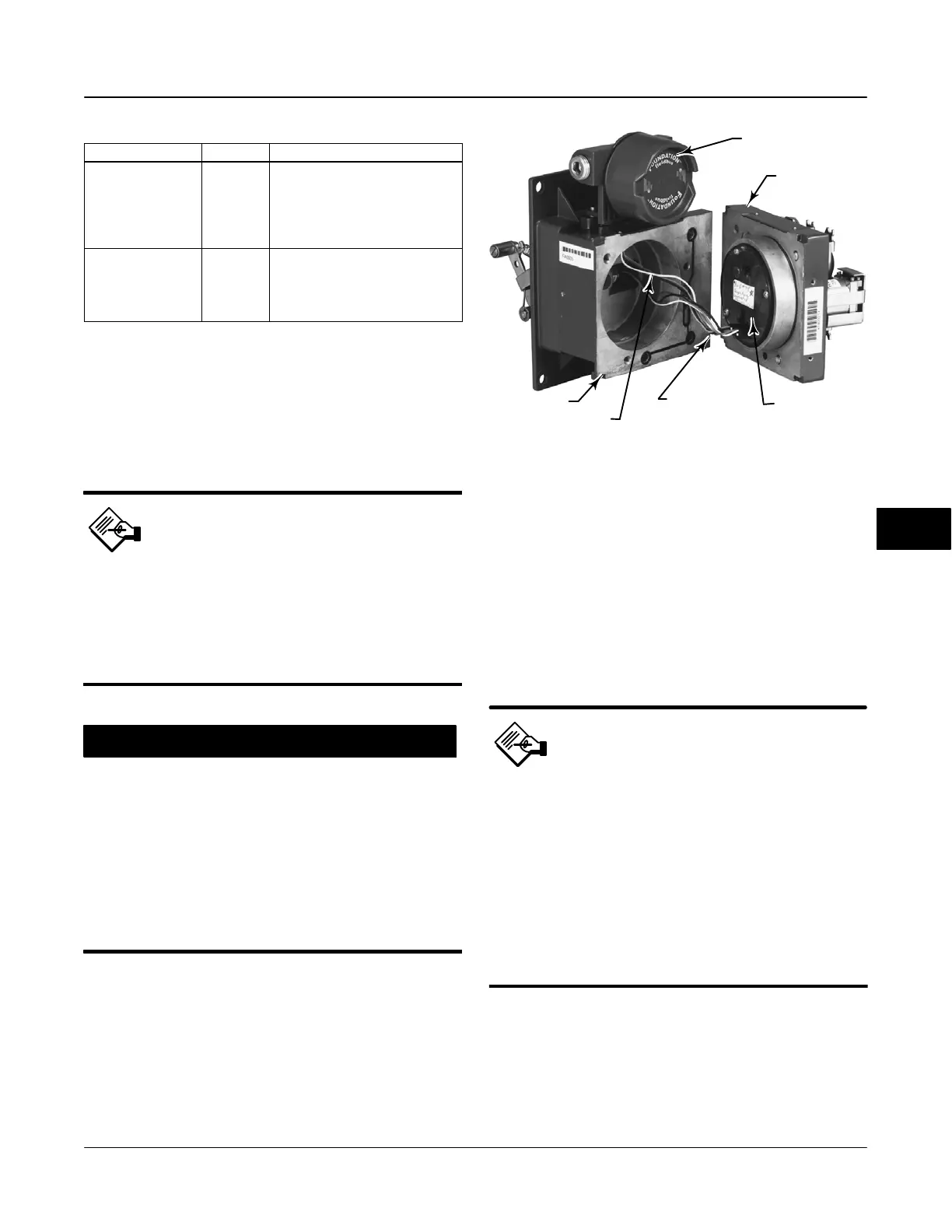
5. The digital valve controller has two cable
assemblies, shown in figure 7-1, which connect the
module base, via the printed wiring board assembly, to
the travel sensor and the terminal box. Disconnect
Figure 7-1. Printed Wiring Board Cable Connections
TERMINAL BOX
MODULE BASE
ASSEMBLY
PRINTED WIRING
BOARD ASSEMBLY
HOUSING
CABLE TO
TERMINAL BOX
W8073-FF
CABLE TO
TRAVEL SENSOR
these cable assemblies from the printed wiring board
assembly on the back of the module base.
Replacing the Module Base
To replace the module base, for DVC6010f, DVC6020f
and DVC6030f digital valve controllers, perform the
following steps. Refer to figures 8-2, 8-3, and 8-4,
respectively, for key number locations. Refer to figure
7-2 for a view of the back of the PWB assembly
sub-module.
Note
Inspect the guide surface on the
module and the corresponding seating
area in the housing before installing
the module base assembly. To avoid
affecting performance of the
instrument, these surfaces must be
free of dust, dirt, scratches, and
contamination.
Ensure the module base seal is in
good condition. Do not reuse a
damaged or worn seal.
1. Ensure the module base seal (key 237) is properly
installed in the housing (key 1). Ensure the O-ring (key
12) is in place on the module base assembly.
2. Connect the terminal box connector to the PWB
assembly (key 50). Orientation of the connector is
required.
7

 Loading...


