Home
Emerson
Controller
Fisher FIELDVUE DVC6000f
Page 316
Emerson Fisher FIELDVUE DVC6000f - Page 316
384 pages
Manual
To Next Page
To Next Page
To Previous Page
To Previous Page
Loading...
DVC6000f
Digital V
alve Controllers
December 2009
B-10
DVC6010f,
DVC6020f, DVC6030f, DVC6010fS, DVC6020fS, DVC6030fS
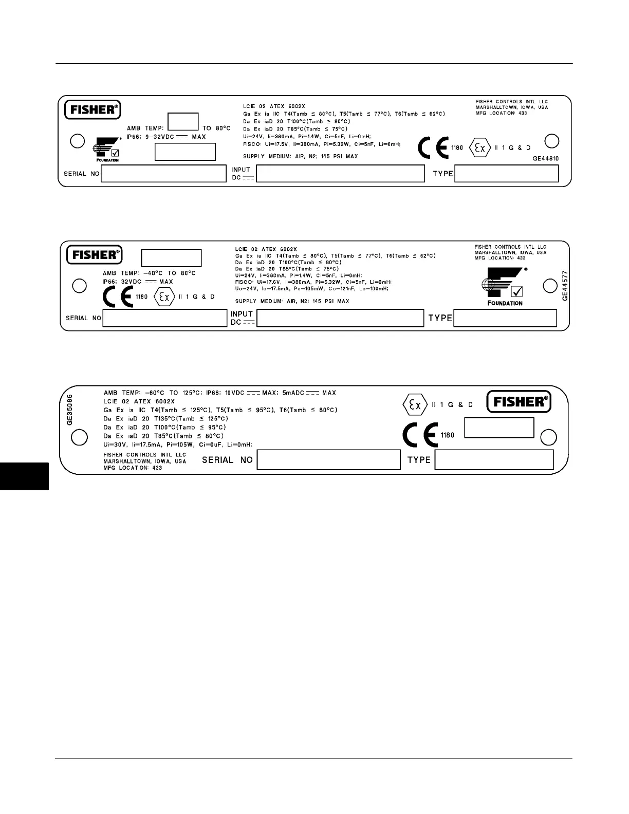
Figure B-11. ATEX Nameplates; Intrinsic Safety, Dust-Tight
DVC6005f
DVC6015, DVC6025, DVC6035
B
315
317
Table of Contents
Main Page
Installation
25
Default Chapter
10
Device Type
10
Hardware Revision
11
Scope of Manual
14
Using this Manual
16
Table of Contents
25
Section 2 Installation
27
Special Instructions for “Safe Use” and
28
Special Instructions for "Safe Use" and Installation in Hazardous Locations
28
Csa
28
Atex
28
Iecex
29
Nepsi
29
Mounting Guidelines
31
Dvc6010F on Sliding-Stem Actuators (up to 4 Inches Travel)
31
Dvc6030F on Quarter-Turn Actuators
35
Dvc6005F Base Unit
38
Wall Mounting
38
Pipestand Mounting
38
DVC6015 on Sliding-Stem Actuators (up to 4 Inches Travel)
38
DVC6035 on Quarter-Turn Actuators
40
Pressure Control
42
Actuator Mounting
42
67CFR Filter Regulator
42
Integral-Mounted Regulator
42
Yoke-Mounted Regulator
42
Casing-Mounted Regulator
43
Pressure Connections
43
Supply Connections
43
Output Connections
43
Single-Acting Actuators
44
Double-Acting Actuators
44
Vent Connections
45
Electrical Connections
46
Fieldbus Connections
46
Basic Setup
47
Feedback Unit Connections for Remote Mounting
48
Detailed Setup
52
Parts
60
Section 2
128
Analog Output (AO) Function Block Overview
129
Modes
129
Mode Handling
130
Shed with Return Options
130
Shed with no Return Options
130
Setting the Output
131
Output Block PV Status
132
Status Handling
131
Action on Fault Detection
132
Set Point Selection and Limiting
132
I/O Options
133
Simulation
133
View Lists
140
Field Communicator Menu Structure
140
Section 3
162
Direct Selection of Inputs
167
Disabling Inputs
167
Input Selection
167
STATUS_OPTS Supported
167
Alarm Detection
168
Block Errors
168
Identification of Selected Inputs
168
View Lists
175
Field Communicator Menu Structure
175
Section 4
200
Default Chapter
201
Modes
201
Multiple Analog Input (MAI) Function Block Overview
201
Application Information
202
Troubleshooting
202
Block Errors
202
View Lists
206
Field Communicator Menu Structure
206
Section 5
208
Discrete Output (DO) Function Block Overview
209
Modes
209
Block Initialization
210
Mode Handling
210
Status Handling
210
I/O Selection
211
Setting the Output
211
Action on Fault Detection
212
Block Errors
212
Simulation
213
View Lists
218
Field Communicator Menu Structure
218
Section 6
220
Default Chapter
221
Block Initialization
221
Discrete Input (DI) Function Block Overview
221
I/O Selection
221
Valve Travel
222
Open/Closed Limit Switch
222
Variable Limit Switch
222
Valve Position Proximity Detection
223
Modes
221
Status Handling
221
Alarm Detection
223
Field Value Processing
223
Block Errors
224
Action on Failure
224
Simulation
224
Application Information
225
View Lists
230
Field Communicator Menu Structure
230
Calibration
247
Section 5 Calibration
248
Travel Calibration
248
Calibration
248
Auto Calibration
248
Manual Calibration
248
Relay
250
Double-Acting Relay
250
Travel Sensor
251
Single-Acting Relays
251
Single-Acting Direct Relay
251
Single-Acting Reverse Relay
251
Dvc6010F, DVC6015, Dvc6030F and DVC6035 Digital Valve Controllers
251
Dvc6020F and DVC6025 Digital Valve Controllers
252
Maintenance and Troubleshooting
267
Module Base Maintenance
270
Removing the Module Base
270
Replacing the Module Base
271
Submodule Maintenance
272
Replacing the I/P Filter
272
Removing the I/P Converter
272
Replacing the I/P Converter
273
Removing the Printed Wiring Board Assembly
273
Pneumatic Relay
274
Removing the Pneumatic Relay
274
Replacing the Pneumatic Relay
274
Gauges, Pipe Plugs or Tire Valves
274
Terminal Box
275
Removing the Terminal Box
275
Replacing the Terminal Box
275
Travel Sensor
276
Related product manuals
Emerson Fisher FIELDVUE DVC6000
162 pages
Fisher FIELDVUE DVC6000 HW2
120 pages
Fisher FIELDVUE DVC6005 Series
30 pages
Emerson Fisher Fieldvue DVC6030f
376 pages
Emerson Fisher Fieldvue DVC6010f
376 pages
Emerson Fisher Fieldvue DVC6020f
376 pages
Emerson Fisher FIELDVUE DVC6215
72 pages
Fisher FIELDVUE DVC6200 SIS
26 pages
Fisher FIELDVUE DVC6200 HW2
6 pages
Fisher FIELDVUE DVC6200 HW1
72 pages
Fisher FIELDVUE DVC6200 Series
44 pages
Emerson Fisher FIELDVUE DVC2000
106 pages