November 2022
Installation, Operation and Maintenance Manual
MAC050515 EN Rev. 0
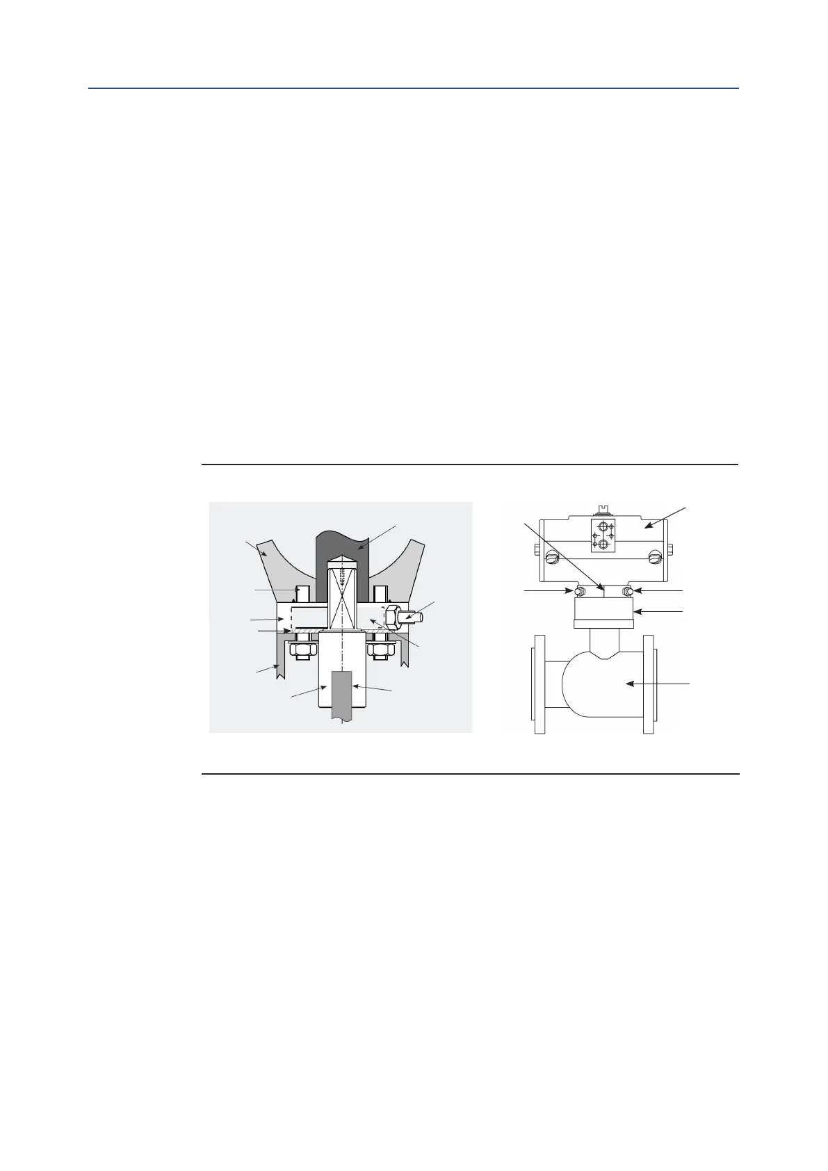
23Bottom Mounted Stop Block
Section 11: Bottom Mounted Stop Block
Figure 9 Stop block mounting arrangement
11.5.2 Stop Adjustment (Fail Closed)
11.5.2.1 Adjustment for the Closed Position
The LEFT hand stop “A” adjusts the CLOSED position. Screw the stop in until it meets the
stop face on the quadrant. The actuator and valve can now be set to the desired position
by adjusting the stop bolt. When the correct position is reached, tighten up the lock nut
against the block face to stop the stop bolt from working loose. The amount of adjustment
is -30° to +70°.
11.5.2.2 Adjustment for the Open Position
Open the valve. The RIGHT hand stop “B” (refer to Figure 8) adjusts the OPEN position.
Screw the stop in until it meets the stop face on the quadrant. The actuator and valve
can now be set to the desired position by adjusting the stop bolt. When the correct
position is reached, tighten up the lock nut against the block face to stop the stop bolt
from working loose. The amount of adjustment is -30° to +70°.
Actuator Body
Studs
Stop Block
Mounting
Bracket
Washer
Valve Stem
Long Shaft
Adaptor
Quadrant
Stop
Bolts
Actuator Pinion
(a) (b)
Actuator
Stop “B”
Bracket
Valve
Stop “A”
Bottom Mounted
Stop Block

 Loading...