June 2022
Installation, Operation and Maintenance Manual
VCIOM-01494-EN Rev. 0
10
Installation
Section 2: Installation
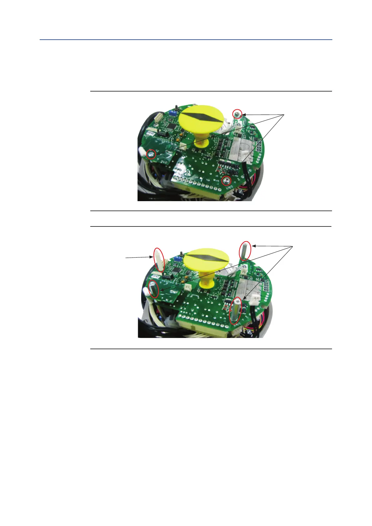
• Unscrew the 3 screws as shown in Figure 17.
• Tighten the 3 metal spacers and the plastic metal spacer as shown in Figure 18.
Figure 17
Figure 18
• Connect OM1 at cable to connector J8 on the logic board as shown in Figure 19.
• Place the OM1 card onto the spares and tighten the 3 screws as shown in Figure 20.
screw
metal spacer
plastic spacer

 Loading...

