June 2022
Installation, Operation and Maintenance Manual
VCIOM-01494-EN Rev. 0
12
Installation
Section 2: Installation
2.4 Assembling Procedure for Models
250-500-1000-2000 Nm New Version
(US or Non-US Market)
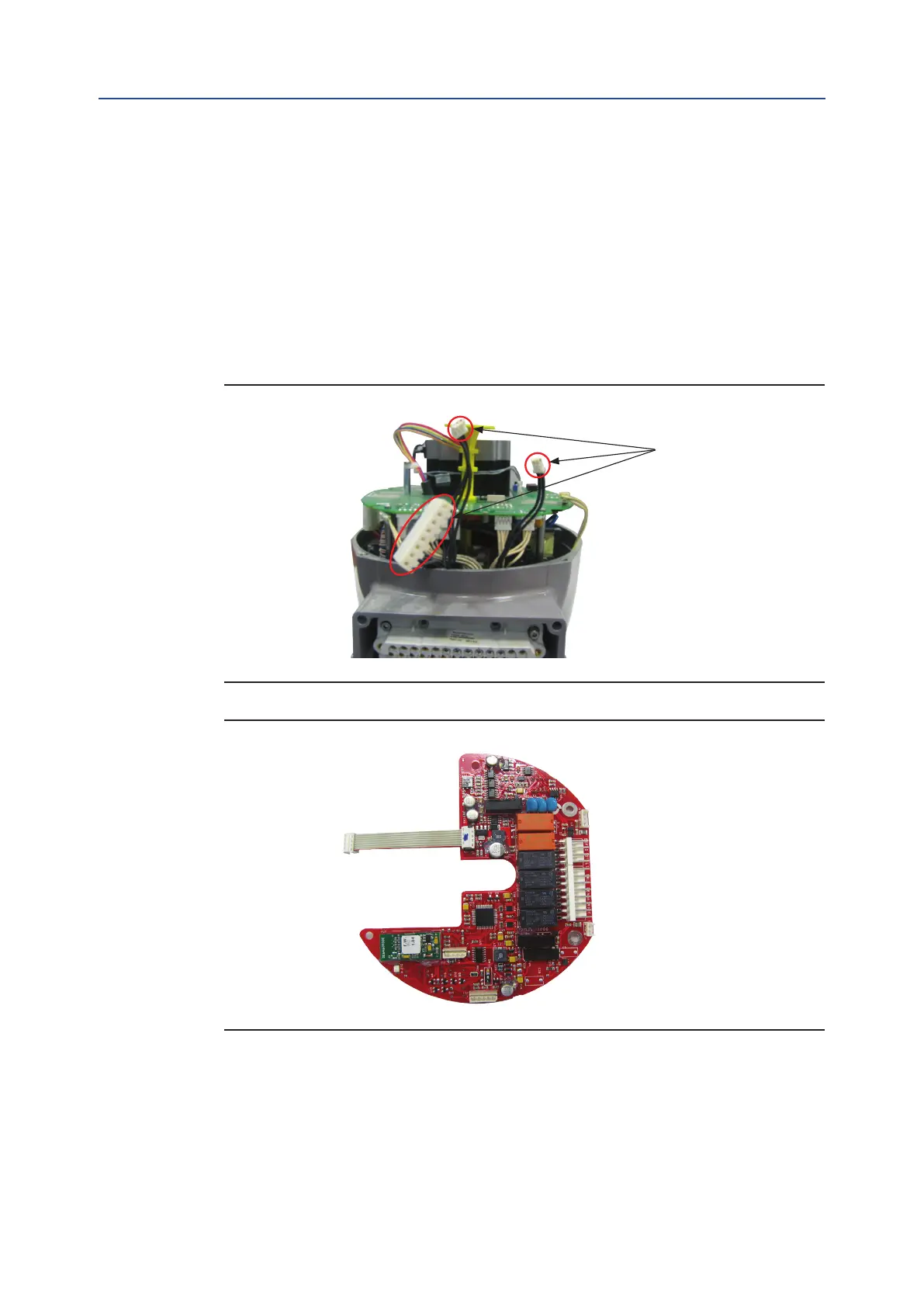
• Detect the 3 black cables required for the OM1 which are already included in the
basic actuator as shown in Figure 22.
• Connect the at cable furnished into the kit to connector J9 on OM1 as shown in
Figure 23.
Figure 22
Figure 23
• Add N
°
3 spacers and unscrew the screw (A) that x the motor cable as shown in
Figure 24.
• Disassemble local mechanical indicator and connect OM1 at cable to connector
on the logic board as shown in Figure 25.
black cables

 Loading...

