24 User Manual 10H52188UM60 - Rev. 2 - 09/2012
Single UPS Installation And Commissioning Liebert NXC
3.3.2 Battery Input (for external Battery)
The overcurrent protective device has been placed in the battery cabinet, when you choose the battery cabinet option
provided by Emerson. Otherwise, the external battery cabinet should provide DC compatible fused circuit breaker, so as to
provide the overcurrent protection for the UPS and its batteries.
3.4 Connecting Power Cables
I/O cables and battery cables are required for connection. When connecting the cables, you should follow the local wiring
regulations, take the environmental situation into account, and refer to Table 3B of IEC/EN 60950-1. The max. current in
different operating modes is listed in Table 3-1, the recommended min. cable CSA is listed in Table 3-2. Select the appropriate
cables according to Table 3-1 and Table 3-2.
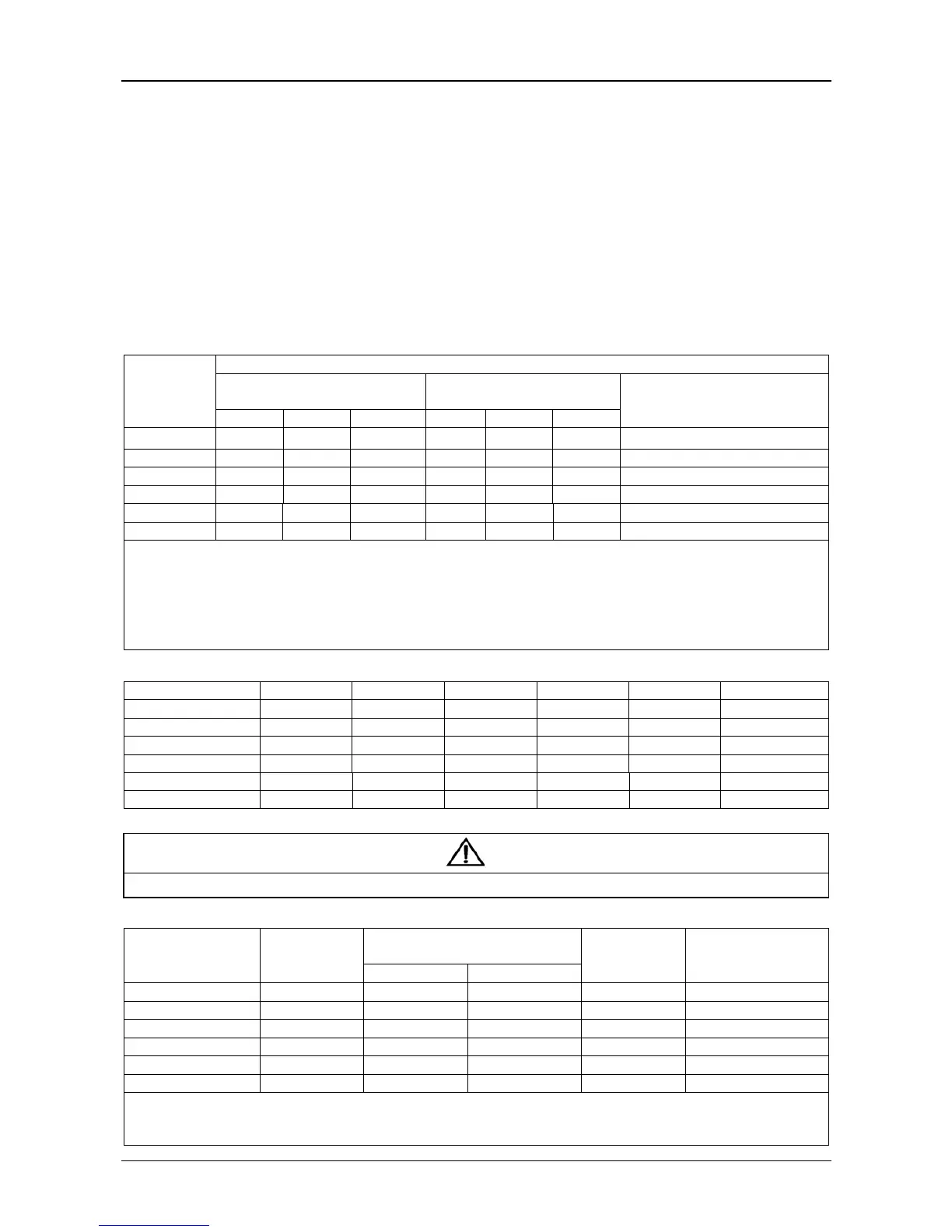
Table 3-1 Max. steady state AC and DC current
UPS rated
power (kVA)
Rated current (A)
Mains input current
1
,
2
upon battery
charging with max. ability
Gross output current
2
at full load
Battery discharging current at min.
battery voltage (EOD)
(30 blocks)
380V 400V 415V 380V 400V 415V
10 (3-in 3-out) 22 21 20 15 15 14
34
10 (3-in 1-out) 22 21 20 45 44 42 34
15 (3-in 3-out) 29 28 27 23 22 21 50
15 (3-in 1-out) 29 28 27 69 65 63 50
20 (3-in 3-out) 37 35 34 30 29 28 67
20 (3-in 1-out) 37 35 34 90 87 84 67
Note:
When selecting the battery cables, according to the current value shown in table, the max. allowable voltage drop is 4Vdc. Do not ring the
cables, so as to avoid increasing the electromagnetic interference (EMI).
1: The mains current input of the rectifier and bypass.
2: Non-linear load (switch mode power) affects the neutral cable design of output and bypass. The neutral cable current may exceed the
rated phase current, in general, 1.732 times as large as the rated current (not applicable, when 3-in 1-out mode)
Table 3-2 Single UPS cable CSA (unit: mm
2
, ambient temperature: 25°C)
Model Input Output Bypass Neutral cable PE Battery
10kVA (3-in 3-out) 4 4 4 4 4 6
10kVA (3-in 1-out) 4 10 10 10 10 6
15kVA (3-in 3-out) 6 6 6 6 6 10
15kVA (3-in 1-out) 6 16 16 16 16 10
20kVA (3-in 3-out) 10 10 10 16 10 16
20KVA (3-in 1-out) 10 25 25 25 16 16
The recommended UPS input MCB capability is listed in Table 3-3, select the MCBs according to your requirements.
Note
The UPS is high leakage current equipment, it is not recommended to configure the MCB with leakage current protection function.
Table 3-3 UPS MCB selection
Model Input interface
Recommended capability of input
external MCB
Battery MCB Output interface
Main Bypass
10kVA (3-in 3-out) Terminal block 32A 32A DC 35A Terminal block
10kVA (3-in 1-out) Terminal block 32A 63A (1P) DC 35A Terminal block
15kVA (3-in 3-out) Teminal block 40A 40A DC 63A Terminal block
15kVA (3-in 1-out) Teminal block 40A 80A (1P) DC 63A Terminal block
20kVA (3-in 3-out) Teminal bock 50A 50A DC 80A Terminal block
20kVA (3-in 1-out) Teminal block 50A 100A (1P) DC 80A Terminal block
Note:
The 3-in 1-out MCB (125A) is used to connect the bypass input upon split-bypass configuration. The main MCB (63A) can be used only
upon common source configuration