User Manual 10H52188UM60 - Rev. 2 - 09/2012 55
Liebert NXC Communication
Chapter 7 Communication
This chapter briefly introduces the UPS communication.
The communication ports include: Intellislot cards port, opto-coupled port, dry contact port and USB port.
7.1 Installing Intellislot cards
7.1.1 Intellislot card Port
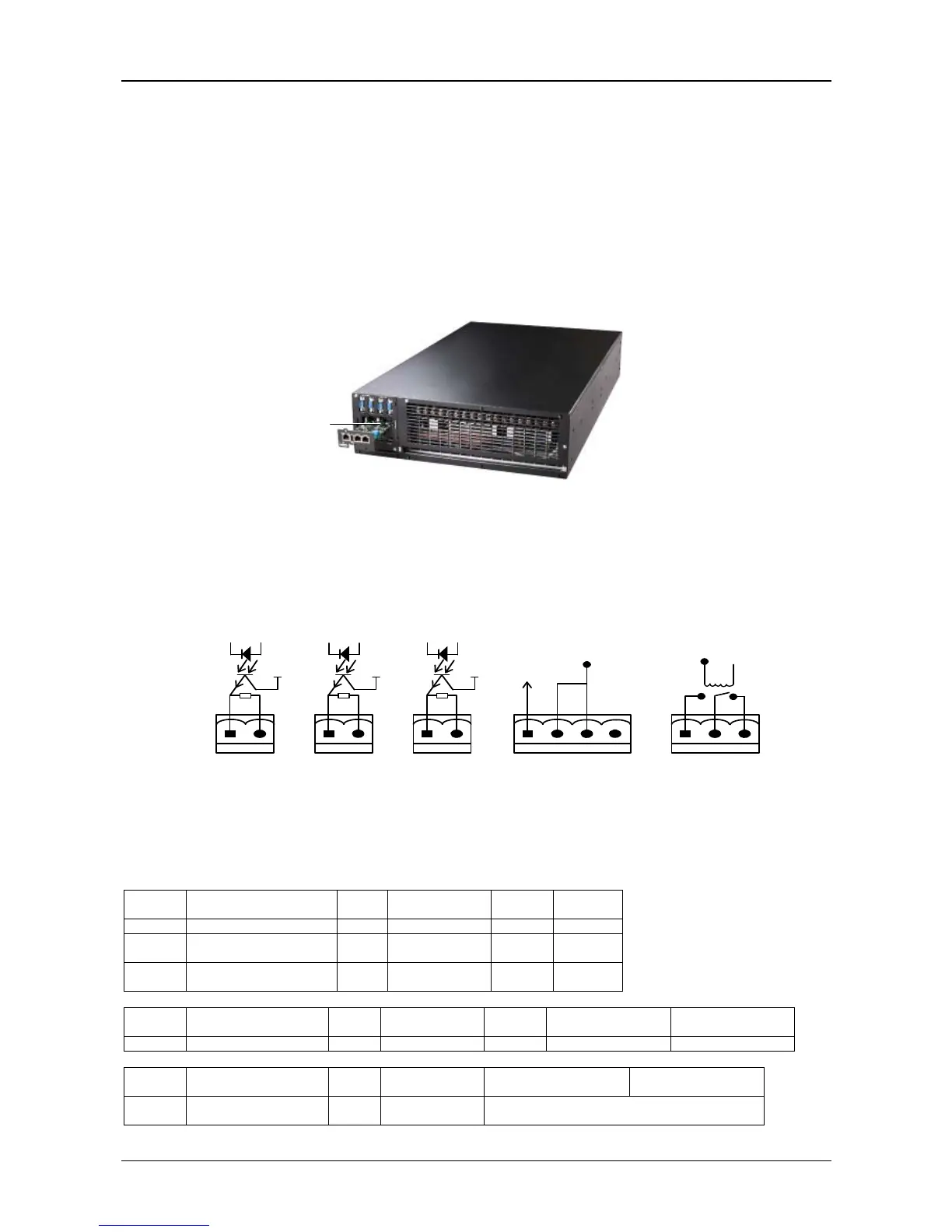
UPS provides an Intellislot card port (see Figure 7-1), which is used to install the communication device options, including
global connectivity cards and LIFE.net adapter. The Intellislot card port and USB port can be used at the same time.
Figure 7-1 Intellislot card installation
Refer to UPS Extended Dry Contact Card User Manual for the installation and operation guide.
7.2 Connection cables for dry contact port and opto-coupled port
The UPS provides two dry contact ports and three opto-coupled ports; see Figure 1-3 for the specific positions. The silk prints
of the five ports are 1, 2, 3, 4 and 5. The pin layout of each port is shown in Figure 7-2, and the port description is shown in
Figure 7-1. Cable cross-sectional are 0,1-1,5mm
2
.
+12V +12V +12V
SALARM
GND
On_battery
GND
On_bapass
GND
Epo_NC
+12V
+12V
Epo_IN
BFP_o
BFP_s
BFP_c
Figure 7-2 Pin layout of dry contact and opto-coupled ports
Port n. Description
Signal
type
Who supply the
power of signal
Rated
voltage
Rated
current
1 Output port of alarm output NXC port 1 12V DC 10mA
2
Output port of battery
status
output NXC port 2 12V DC 10mA
3
Output port of bypass
status
output NXC port 3 12V DC 10mA
Port n. Description
Signal
type
Who supply the
power of signal
Rated
voltage
Maximal resistance
of EPO_NO
Maximal resistance
of EPO_NC
4 Input port of remote EPO input NXC port 4 12V DC 10Ohm 10Ohm
Port n. Description
Signal
type
Who supply the
power of signal
Rated voltage and
current for NO contact
Rated voltage and
current for NC contact
5
Output port of bypass
backfeed
output External 5A 250V AC/24V DC
Intelligent card port
Opto-coupled port 1 Opto-coupled port 2 Opto-coupled port 3 Dry contact port 4 Dry contact port 5