2 Planning
2.1 Installation checklist
□ Make sure that the hazardous area specified on the approval tag is suitable for the
environment in which the meter will be installed.
WARNING
Failure to abide by approvals can cause an explosion resulting in injury or death.
□ Verify that the local ambient and process temperatures are within the limits of the
meter.
□ If your sensor has an integral transmitter, no wiring is required between the sensor and
transmitter. Follow the wiring instructions in the transmitter installation manual for
signal and power wiring.
□ If your transmitter has remote-mounted electronics, follow the instructions in this
manual for wiring between the sensor and the transmitter, and then follow the
instructions in the transmitter installation manual for power and signal wiring.
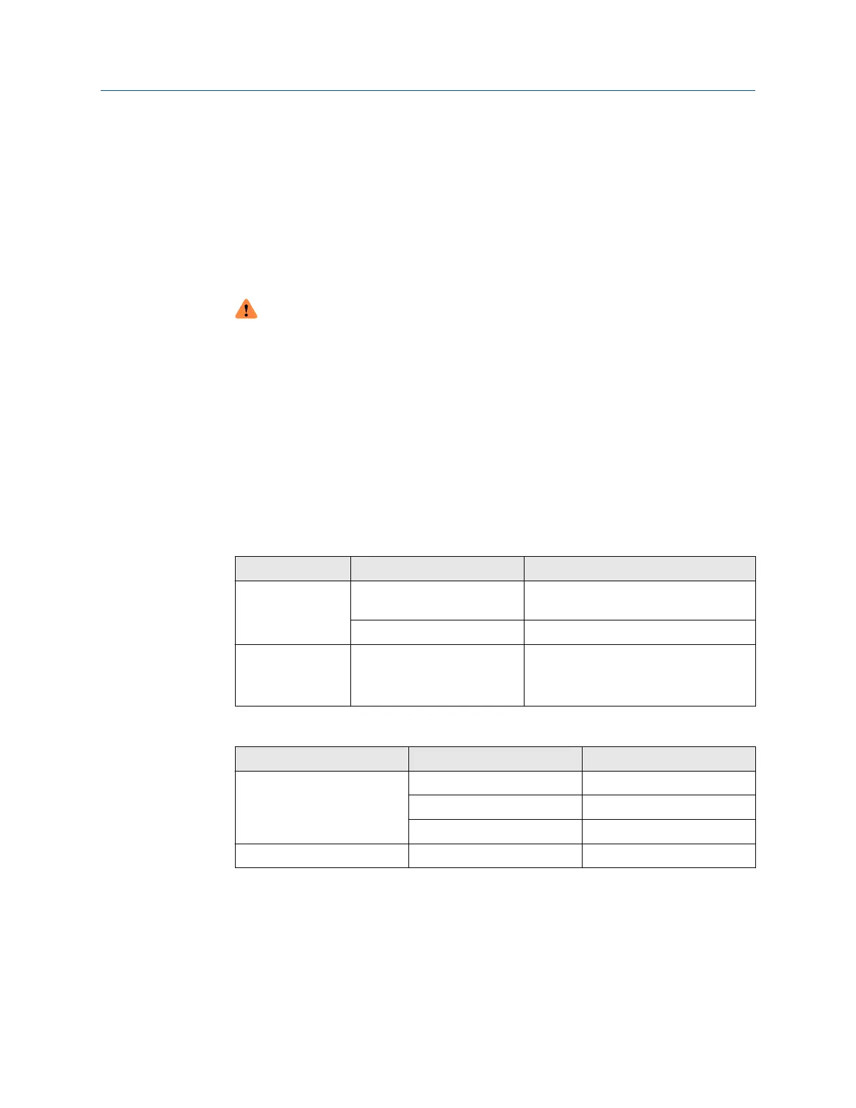
Table 2-1: Maximum cable lengths
Cable type To transmitter Maximum length
Micro Motion
9-wire
9739 MVD and 5700
transmitter
1,000 ft (305 m)
All other MVD transmitters 60 ft (18 m)
Micro Motion
4-wire
All 4-wire MVD transmitters 1,000 ft (305 m) without Ex-approval
500 ft (152 m) with IIC-rated sensors
1,000 ft (305 m) with IIB-rated sensors
Table 2-2: Maximum lengths for user-supplied 4-wire cable
Wire function Wire size Maximum length
Power (VDC) 22 AWG (0.326 mm²) 300 ft (91 m)
20 AWG (0.518 mm²) 500 ft (152 m)
18 AWG (0.823 mm²) 1,000 ft (305 m)
Signal (RS-485) 22 AWG (0.326 mm²) or larger 1,000 ft (305 m)
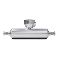
□ For optimal performance, install the sensor in the preferred orientation. The sensor will
work in any orientation as long as the flow tubes remain full of process fluid.
Installation Manual Planning
20002298 April 2020
Installation Manual 7

 Loading...