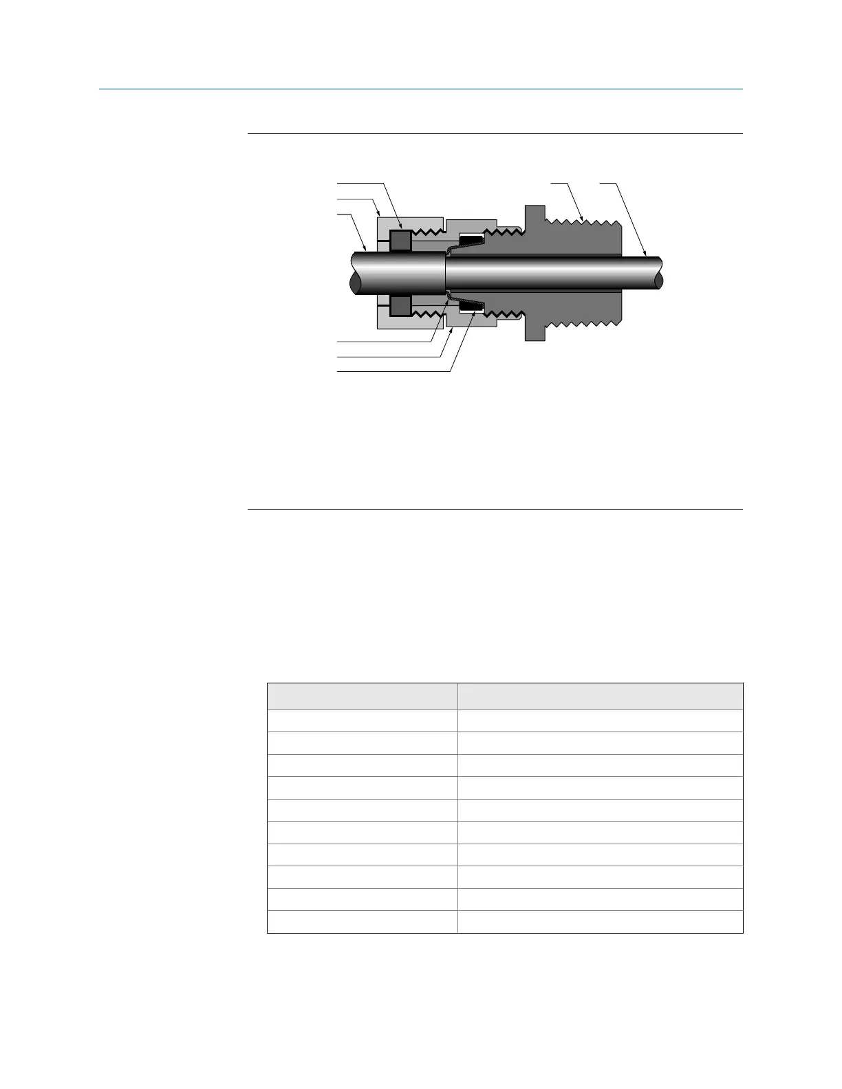
Cross-section of assembled cable gland with cableFigure 3-4:
A. Cable
B. Sealing nut
C. Seal
D. Compression nut
E. Braided shield
F. Brass compression ring
G. Nipple
9. Remove the core processor cover.
10. At the core processor, connect the cable according to the following procedure:
a. Insert the stripped end of each wire into the corresponding terminal at the core
processor ends, matching by color. No bare wires should remain exposed. See
the following table.
Core processor terminal designationsTable 3-2:
Wire color Function
Black Drain wires
Brown Drive +
Red Drive –
Orange Temperature –
Yellow Temperature return
Green Left pickoff +
Blue Right pickoff +
Violet Temperature +
Gray Right pickoff –
White Left pickoff –
Wiring
12 Micro Motion Liquified Natural Gas Meter

 Loading...


