Procedure
Connect the enhanced core processor to the barrier:
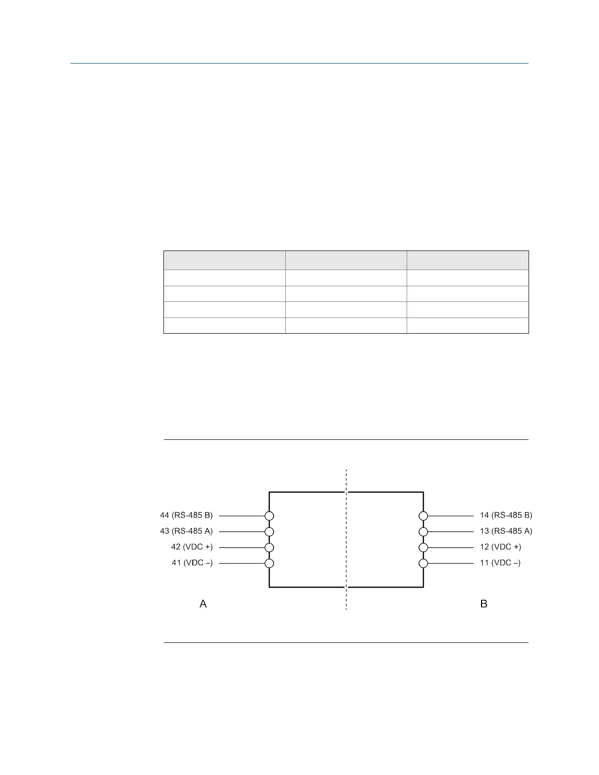
a. Connect the RS-485 wires from the enhanced core processor to the I.S. RS-485
terminals at the barrier (terminals 43 and 44), matching A and B. See the following
table and figure.
b. Connect the power supply wires from the core processor to the I.S. VDC terminals at
the barrier (terminals 42 and 41), matching positive and negative (+ and –). Do not
terminate the shields at the barrier. See the following table and figure.
Enhanced core processor and barrier I.S. terminalsTable 3-3:
Function Core processor terminals Barrier I.S. terminals
RS-485 A 3 43
RS-485 B 4 44
VDC + 1 42
VDC – 2 41
c. Connect the RS-485 wires to the non-I.S. RS-485 terminals at the barrier (terminals 13
and 14). These wires will be used in the next step to connect the barrier to the remote
host. Do not terminate the shields at the barrier.
d. Connect the power supply wires to the non-I.S. VDC terminals at the barrier (terminals
11 and 12). These wires will be used in the next step to connect the barrier to the power
supply.
Barrier terminalsFigure 3-7:
A. I. S. terminals for connection to enhanced core processor
B. Non I.S. terminals for connection to remote host and power supply
Wiring
Quick Start Guide 17