15
emersonfans.com
Please contact 1-800-654-3545 for further assistance
U.L. Model No.: 42-ANT & 52-ANT
To avoid possible fire or shock, make sure that the
electrical wires are completely inside the outlet box
and not pinched between the ceiling cover and the
ceiling.
WARNING
!
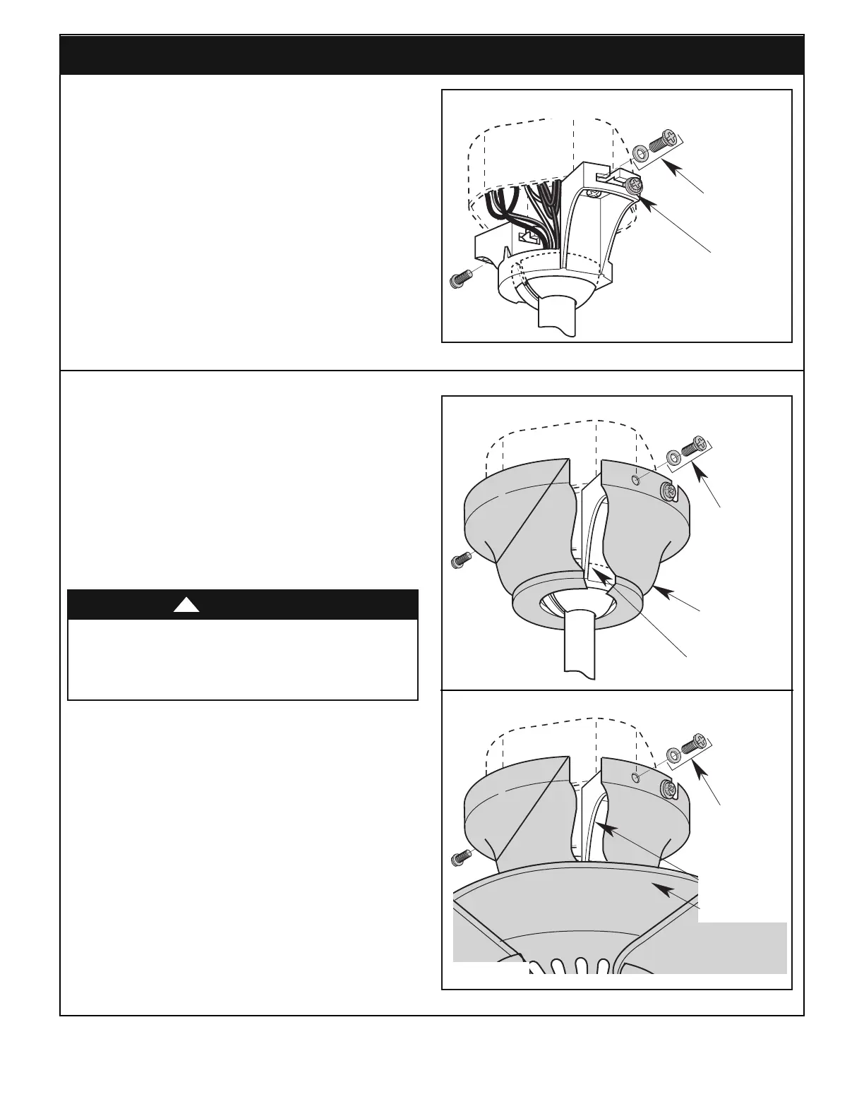
9. Installing the Ceiling Cover
REMOVE LEFT
SCREW AND
LOCKWASHER
ON EACH SIDE
LOOSEN THE RIGHT
SCREW/LOCKWASHER
ON EACH SIDE
Figure 20
9.1
Remove the left screw and lockwasher from each side
of the hanger bracket (Figure 20) and loosen the other
t
wo screws.
NOTE: When installing the ceiling fan using the
c
lose-to-the-ceiling method, carefully lift the fan
assembly from the hook on the hanger bracket and
proceed as follows.
CLOSE-TO-THE-CEILING ASSEMBLY
REINSALL LEFT
SCREW AND
LOCKWASHER
ON EACH SIDE
HANGER BRACKET
CEILING COVER
HANGER BALL/DOWNROD ASSEMBLY
CEILING COVER
HANGER
BRACKET
REINSALL LEFT
SCREW AND
LOCKWASHER
ON EACH SIDE
Figure 21
9.2
Lift the ceiling cover up to the hanger bracket. Engage
the slots in the ceiling cover with the loosened screws
in the bracket and turn the cover counterclockwise
(Figure 21).
Be sure that the lockwashers are between the screw
heads and the ceiling cover.
Install the other two screws and lockwashers; tighten all
screws securely.
Hanger Ball/Downrod Assembly Shown
 Loading...