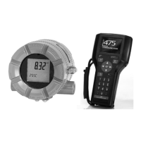
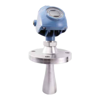
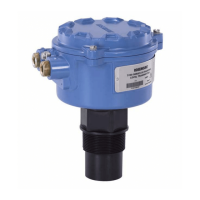
Product Data Sheet
00813-0100-4530, Rev DA
December 2010
29
Rosemount 5300 Series
TABLE 7. Transition Zones
Measuring Range and
Minimum Dielectric Constant
16 in. (0.4 m) to 164 ft (50 m)
See Table 8 on page 30 for each probe’s measuring range and minimum dielectric constant. Due to
the measuring range depending on the application and factors described below, the values are a
guideline for clean liquids. For more information, ask your local Emerson Process Management
representative
Different parameters (factors) affect the echo and therefore the maximum measuring range differs
depending on application according to:
• Disturbing objects close to the probe
• Media with higher dielectric constant (
r
) gives better reflection and allows a longer measuring range
• Surface foam and particles in the tank atmosphere may affect measuring performance
• Heavy coating or contamination on the probe should be avoided since it can reduce measuring
range and might cause erroneous level readings
Note: For Remote Housing, see Table 9 on page 30 for the maximum recommended measuring
range for different Remote Housing lengths, installation types, Dielectric Constants, and probe types
Interface Measuring Range Target applications include interfaces between oil / oil-like and water / water-like liquids with low (<3)
upper product dielectric constant and high (>20) lower product dielectric constant.
For such applications, the maximum measuring range is only limited by the length of the rigid single
lead, coaxial, and rigid twin probes.
For the flexible probes, the maximum measuring range will be reduced based on the maximum upper
product thickness according to the diagram below. The maximum interface distance is 164 ft (50 m)
minus the maximum product thickness.
For information on the maximum allowable product thickness and measuring range, see graphs on
page 27
Environment
Vibration Resistance Aluminum housing: IEC 60770-1 Level 1. Stainless Steel housing: IACS E10
Electromagnetic Compatibility Emission and Immunity: EMC directive 89/336/EEC. EN61326-1:1997 incl. A1:1998 and A2:2001.
NAMUR recommendations NE21
Built-in Lightning Protection EN61326, IEC 801-5, level 1 kV. T1 option: the transmitter complies with IEEE 587 Category B
transient protection and IEEE 472 surge protection
Coating
(See Table 10 on page 30)
• Single lead probes are preferred when there is a risk of contamination (because coating can result
in the product bridging across the two leads for twin versions; between the inner lead and outer
pipe for the coaxial probe)
• For viscous or sticky applications, PTFE probes are recommended. Periodic cleaning may also be
required
•
Signal Quality Metrics (option code D01, or DA1) can be used in determining when to clean the probe
Transmitters equipped with the Diagnostics Suite option can calculate Signal Quality Metrics
• Maximum error due to coating is 1-10% depending on probe type, dielectric constant, coating
thickness and coating height above product surface
CE-mark Complies with applicable directives (EMC, ATEX)
(1) For probes with spacers, the accuracy may deviate close to the spacers. Accuracy may be affected by remote housing.
Dielectric Constant Rigid Single Lead Flexible Single Lead Coaxial Rigid Twin Lead Flexible Twin Lead
Upper
(1)
Transition
Zone
80 4.3 in. (11 cm) 4.3 in. (11 cm) 4.3 in. (11 cm) 4.3 in. (11 cm) 4.7 in. (12 cm)
2 6.3 in. (16 cm) 7.1 in. (18 cm) 4.3 in. (11 cm) 5.5 in. (14 cm) 5.5 in. (14 cm)
Lower
(2)
Transition
Zone
80 2 in. (5 cm) 0 in. (0 cm)
(4)
(3)
0.4 in. (1 cm) 1.2 in. (3 cm) 2 in. (5 cm)
(4)
2 2.8 in. (7 cm)
(5)
2 in. (5 cm) - long
weight
(4)
3.2 in. (8 cm) - short
weight
(4)
2 in. (5 cm) 4 in. (10 cm) 5.5 in. (14 cm)
(4)
Note: The 4–20 mA set points are recommended to be configured between the transition zones, within the measuring range.
(1) The distance from the upper reference point where measurements have reduced accuracy.
(2) The distance from the lower reference point where measurements have reduced accuracy.
(3) The measuring range for the PTFE covered Flexible Single Lead probe includes the weight. For low dielectric media, special configuration may be required.
(4)
Note that the weight length or chuck fastening length adds to non-measurable area and is not included in the diagram. See “Dimensional Drawings” on page 39.
(5) When using a metallic centering disc, the lower transition zone is 8 in. (20 cm), including weight if applicable. When using a PTFE centering disc, the lower
transition zone is not affected.

 Loading...

