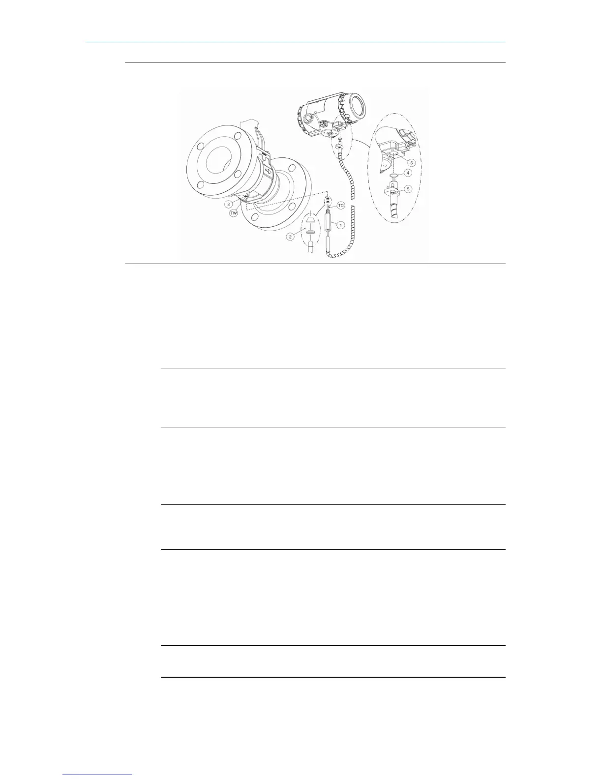
Figure 2-8: Thermocouple assembly
Procedure
1. Slide the thermocouple bolt (1) over the thermocouple (TC).
2. Place the 2-part ferrule (2) over the end tip of the thermocouple (TC).
3. Insert the thermocouple in to the thermowell hole (TW) on the
bottom side of the meter body.
Important
Carefully push the thermocouple in to the thermowell completely.
This is critical to get the proper insertion depth. Then thread the
thermocouple bolt in to the hole.
4. When the thermocouple bolt is hand tight, mark the position of the
bolt in relation to the meter body (the mark will help determine
rotations). Using a ½-in. wrench turn the bolt clockwise ¾ turn to seat
the ferrule.
Note
After completing Step 4, the ferrule and thermocouple bolt will be
permanently installed on the thermocouple.
5. Verify the rubber O-ring is installed on the electronics connection end
of the thermocouple.
6. Verify the 2.5 mm hex head screw is installed.
7. Insert the electronics end connector in to the transmitter housing.
Tighten the screw with a 2.5 mm hex bit to secure the connection.
Important
Do not over tighten hex screw.
Quick Start Guide October 2018
10 Rosemount
™
8800D Series Vortex Flowmeter

 Loading...