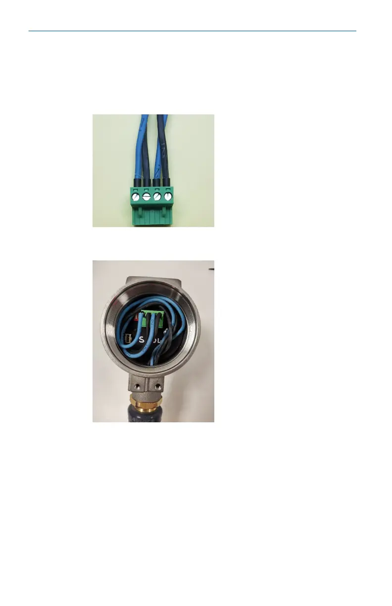
3. Remove the connector from the socket inside the device.
Connect the four conductors into the connector ensuring
that they match the power and data connections from the
control system side. The connections from left to right are:
Communication –ve, Communication +ve, Power –ve, Power
+ve.
4. Insert the connector into the socket in the device with the
excess wire looped around the inside of the device housing.
Quick Start Guide May2024
32 Emerson.com/Rosemount