Safety
Information
Introduction
Product
information
System
design
Mechanical
installation
Electrical
installation
Getting
started
Optimisation
Parameters
Techn i cal
data
Component
sizing
Diagnostics
Unidrive SP Regen Installation Guide 121
Issue Number: 2 www.controltechniques.com
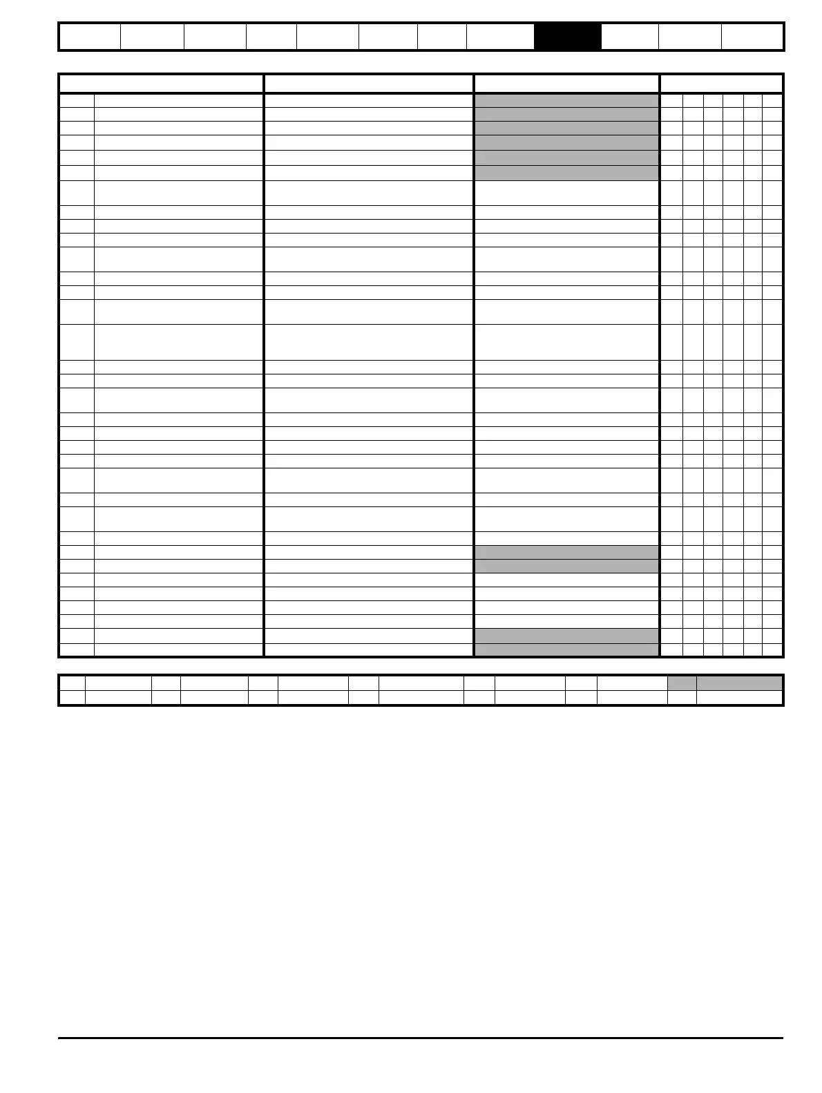
Menu 7 Regen parameter descriptions
Parameter
Range(
Ú) Default(Ö)
Type
7.01 T5/6 analogue input 1 level ±100.00 % RO Bi NC PT
7.02 T7 analogue input 2 level ±100.0 % RO Bi NC PT
7.03 T8 analogue input 3 level ±100.0 % RO Bi NC PT
7.04 Stack temperature 1
-128 to 127
°C
RO Bi NC PT
7.05 Stack temperature 2
-128 to 127
°C
RO Bi NC PT
7.06 Control board temperature
-128 to 127
°C
RO Bi NC PT
7.07
T5/6 analogue input 1 offset
trim
{
0.13} ±10.000 % 0.000 RW Bi US
7.08 T5/6 analogue input 1 scaling 0 to 4.000 1.000 RW Uni US
7.09 T5/6 analogue input 1 invert OFF (0) or On (1) OFF (0) RW Bit US
7.10 T5/6 analogue input 1 destination Pr 0.00 to 21.51 Pr 0.00 RW Uni DE PT US
7.11 T7 analogue input 2 mode {0.19}
0-20 (0), 20-0 (1), 4-20.tr (2), 20-4.tr (3),
4-20 (4), 20-4 (5), VOLt (6)
VOLt (6) RW Txt US
7.12 T7 analogue input 2 scaling 0 to 4.000 1.000 RW Uni US
7.13 T7 analogue input 2 invert OFF (0) or On (1) OFF (0) RW Bit US
7.14
T7 analogue input 2
destination
{
0.20}Pr 0.00 to 21.51 Pr 3.10 RW Uni DE PT US
7.15 T8 analogue input 3 mode {0.21}
0-20 (0), 20-0 (1), 4-20.tr (2), 20-4.tr (3),
4-20 (4), 20-4 (5), VOLt (6), th.SC (7),
th (8), th.diSP (9)
VOLt (6) RW Txt US
7.16 T8 analogue input 3 scaling 0 to 4.000 1.000 RW Uni US
7.17 T8 analogue input 3 invert OFF (0) or On (1) OFF (0) RW Bit US
7.18
T8 analogue input 3
destination
Pr
0.00 to 21.51 Pr 0.00 RW Uni DE PT US
7.19 T9 analogue output 1 source Pr 0.00 to 21.51 Pr 4.01 RW Uni PT US
7.20 T9 analogue output 1 scaling 0.000 to 4.000 1.000 RW Uni US
7.21 T9 analogue output 1 mode VOLt (0), 0-20 (1), 4-20 (2), H.SPd (3) VOLt (0) RW Txt US
7.22 T10 analogue output 2 source Pr 0.00 to 21.51 Pr 5.05 RW Uni PT US
7.23
T10 analogue output 2
scaling
0.000 to 4.000 1.000 RW Uni US
7.24 T10 analogue output 2 mode VOLt (0), 0-20 (1), 4-20 (2), H.SPd (3) VOLt (0) RW Txt US
7.25
Calibrate T5/6 analogue input 1 full
scale
OFF (0) or On (1) OFF (0) RW Bit NC
7.26 T5/6 analogue input 1 sample time 0 to 8.0 ms 4.0 RW Uni US
7.28 T7 analogue input 2 current loop loss OFF (0) or On (1) RO Bit NC PT
7.29 T8 analogue input 3 current loop loss OFF (0) or On (1) RO Bit NC PT
7.30 T5/6 analogue input 1 offset ±100.00 % 0.00 RW Bi US
7.31 T7 analogue input 2 offset ±100.0 % 0.0 RW Bi US
7.32 T8 analogue input 3 offset ±100.0 % 0.0 RW Bi US
7.33 T9 analogue output 1 control Fr (0), Ld (1), AdV (2) AdV (2) RW Txt US
7.34 IGBT junction temperature
±200
°C
RO Bi NC PT
7.35 Drive thermal protection accumulator 0 to 100.0 % RO Uni NC PT
RW Read / Write RO Read only Uni Unipolar Bi Bi-polar Bit Bit parameter Txt Text string
FI Filtered DE Destination NC Not cloned RA Rating dependent PT Protected US User save PS Power down save