Safety
Information
Introduction
Product
information
System
design
Mechanical
installation
Electrical
installation
Getting
started
Optimisation Parameters
Tec h nic a l
data
Component
sizing
Diagnostics
Unidrive SP Regen Installation Guide 67
Issue Number: 2 www.controltechniques.com
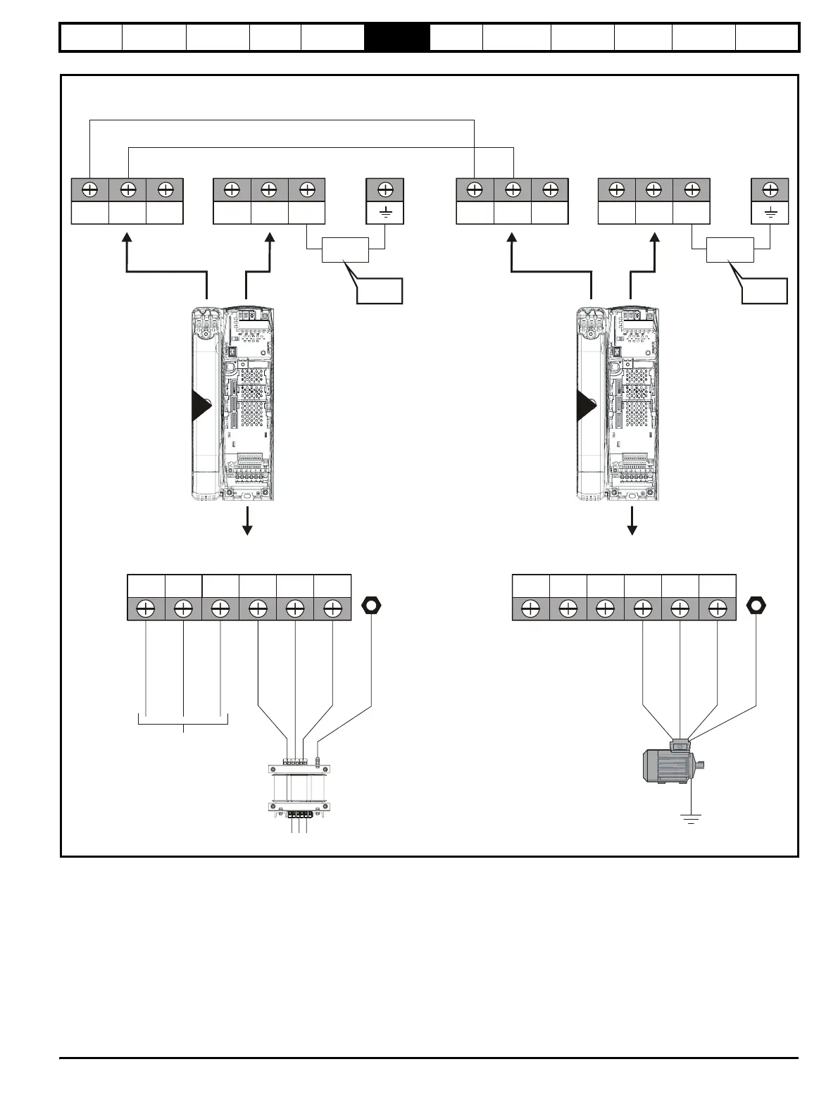
Figure 6-2 Unidrive SP size 2 power connections
If the heatsink mounted resistor is used (size 1 and 2 only), an overload
protection device is not required. The resistor is designed to fail safely
under fault conditions.
See Figure 6-8 for further information on ground connections.
2
L2L1 L3 U V W PE
AC supply connections
BRDC1 DC2 48V -DC +DC
Internal
EMC filter
DC1 =
DC2 = +
-
To be
removed
L1, L2, L3
(Refer to Chapter 4
)System design
2
L2L1 L3 U V W PE
BRDC1 DC2
D
connections
(High current DC to motoring drive[s])
48V -DC +DC
Internal
EMC filter
DC1 =
DC2 = +
-
To be
removed
Motor
Optional ground
nn
ti
n
Regen drive
Motoring drive
Vac supply
Motor connections