Safety
Information
Introduction
Product
information
System
design
Mechanical
installation
Electrical
installation
Getting
started
Optimisation
Parameters
Technical
data
Component
sizing
Diagnostics
104 Unidrive SP Regen Installation Guide
www.controltechniques.com Issue Number: 2
The defaults Kp and Ki gains should be suitable for the standard regen inductors.
Setting the current controller gains
The most critical parameter for stability is the current controller proportional gain (Pr 4.13). The required value for this is dependent on the Regen unit
input inductance. If the inductance of the supply is a significant proportion of the recommended regen inductor (i.e. 60/I
DR
mH per phase, where I
DR
is equivalent to Kc), then the proportional gain may need to be increased. The supply inductance is likely to be negligible compared to the regen
inductor value with small drives, but is likely to be significant with larger drives.
The proportional gain Pr 4.13 should be adjusted as described below using the total inductance per phase. The current controller integral gain Pr 4.14
is not so critical, and in a majority of cases the default value is suitable. However, if it is necessary to adjust this parameter it should be set up as
described below using the supply resistance for one phase.
The proportional gain Kp (Pr 4.13) is the most critical value in controlling the performance of the current controllers. The value can be set by the user
so that :
Kp = (L / T) x (I
fs
/ V
fs
) x (256 / 5)
Where:
T is the sample time of the current controllers. The drive compensates for any change of sample time, and so it should be assumed that the sample
time is equivalent to the lowest sample rate of 167µs.
L is the total inductance per phase.
I
fs
is the peak full scale current feedback = Kc x √2 / 0.45. Where Kc is the current scaling for each size of drive.
V
fs
is the maximum DC link voltage.
Therefore:
Kp = (L / 167µs) x (Kc x √2 / 0.45 / V
fs
) x (256 / 5) = K x L x Kc
Where:
K = [√2 / (0.45 x V
fs
x 167µs)] x (256 / 5)
There is one value of the scaling factor K for each drive voltage rating as shown in the table below.
The integral gain Ki (Pr 4.14) is less critical and should be set so that:
Ki = Kp x 256 x T / τ
m
Where:
τ
m
is the time constant (L / R).
R is the resistance of the supply for one phase.
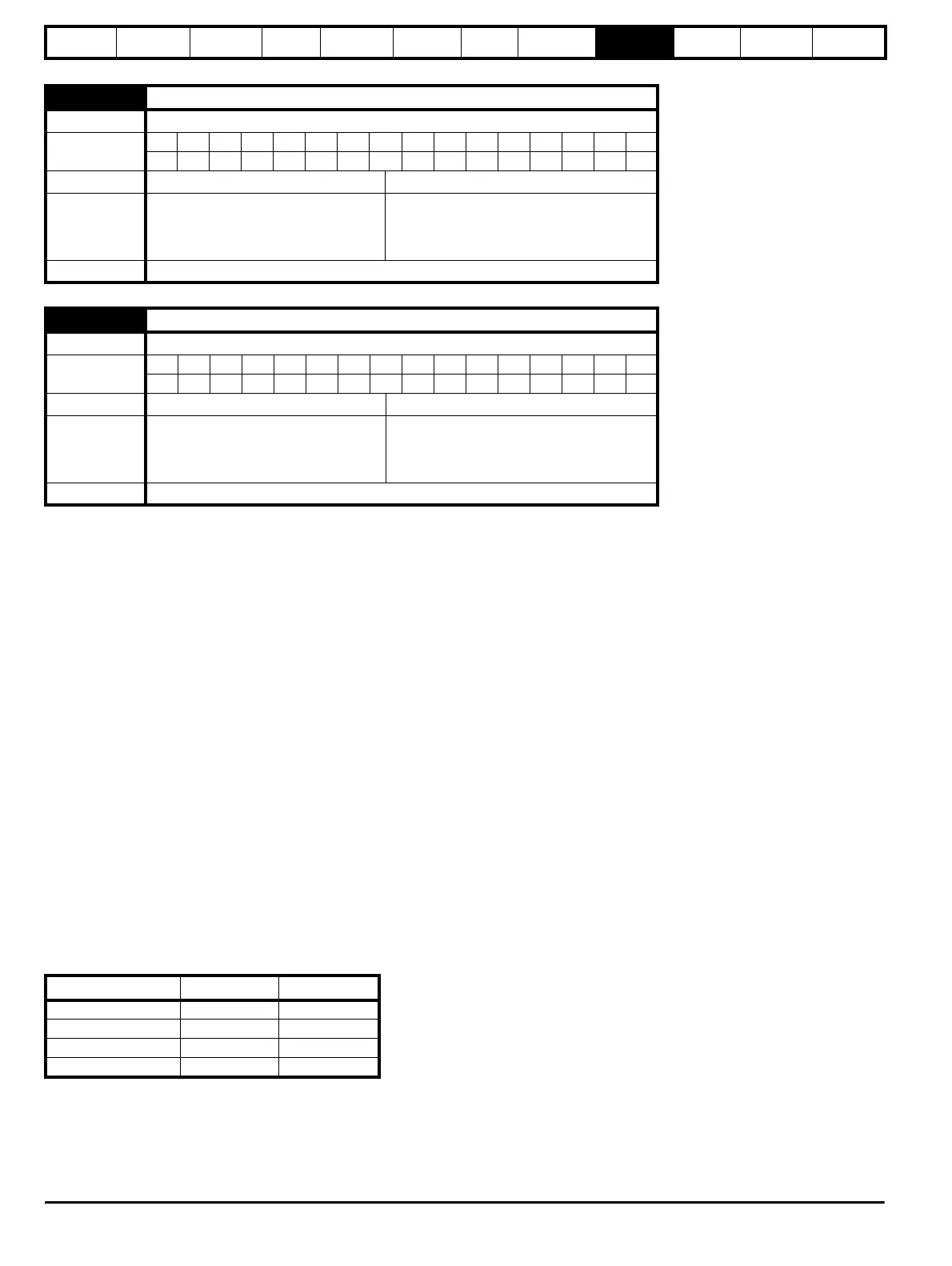
4.13 Current controller Kp gain
Drive mode Regen
Coding
Bit SP FI DE Txt VM DP ND RA NC NV PT US RW BU PS
111
Range Regen 0 to 30,000
Default Regen
200V: 45
400V: 90
575V: 110
690V: 130
Update rate Background
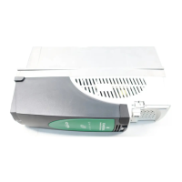
4.14 Current controller Ki gain
Drive mode Regen
Coding
Bit SP FI DE Txt VM DP ND RA NC NV PT US RW BU PS
111
Range Regen 0 to 30,000
Default Regen
200V: 1000
400V: 2000
575V: 2400
690V: 3000
Update rate Background
Drive voltage rating
V
fs
K
200V 415V 2322
400V 830V 1161
575V 990V 973
690V 1190V 809