Safety
Information
Introduction
Product
information
System
design
Mechanical
installation
Electrical
installation
Getting
started
Optimisation Parameters
Tec h nic a l
data
Component
sizing
Diagnostics
Unidrive SP Regen Installation Guide 77
Issue Number: 2 www.controltechniques.com
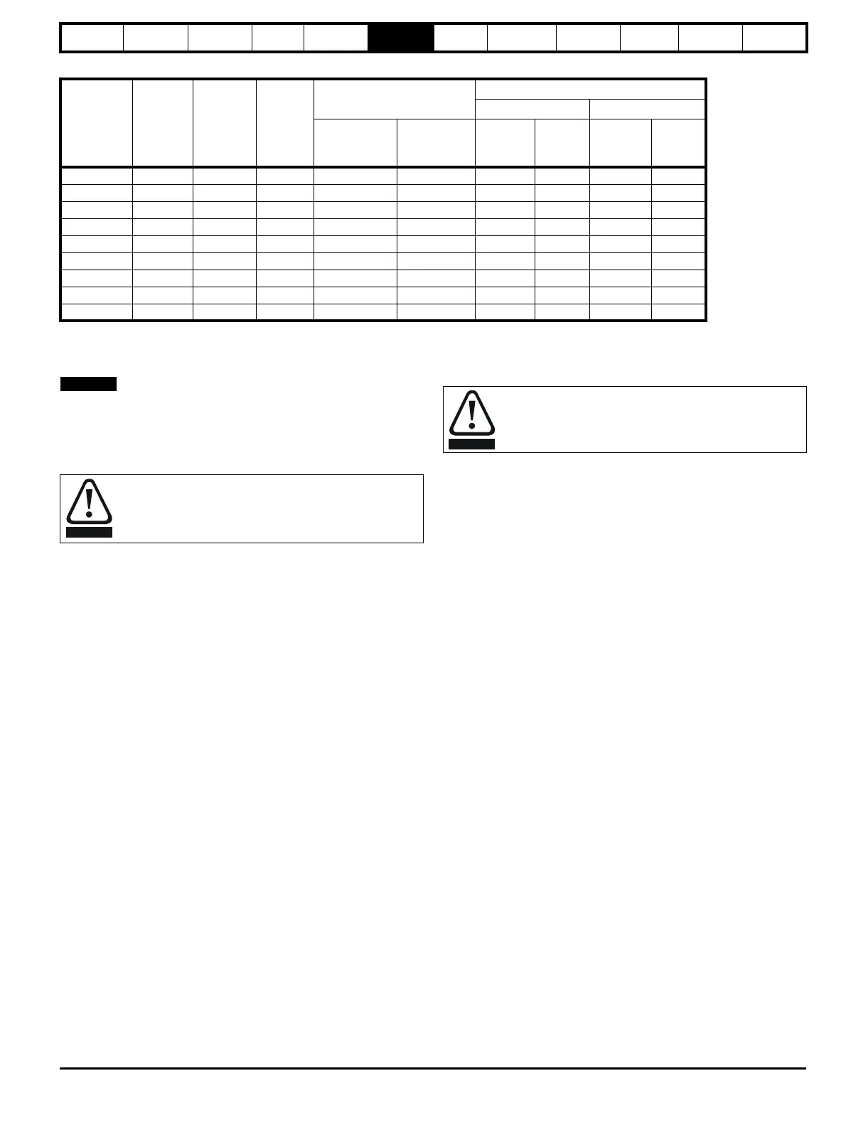
Table 6-5 SPMC / U input current, fuse and cable ratings
The recommended cable sizes above are only a guide. Refer to local
wiring regulations for the correct size of cables. In some cases a larger
cable is required to avoid excessive voltage drop.
N
The recommended cable sizes above are only a guide. The mounting
and grouping of cables affects their current-carrying capacity, in some
cases smaller cables may be acceptable but in other cases a larger
cable is required to avoid excessive temperature or voltage drop. Refer
to local wiring regulations for the correct size of cables.
A fuse or other protection must be included in all live connections to the
AC supply.
An MCB (miniature circuit breaker) or MCCB (moulded-case circuit-
breaker) with type C may be used in place of fuses on Unidrive SP sizes
1 to 3 under the following conditions:
• The fault-clearing capacity must be sufficient for the installation
• For frame sizes 2 and 3, the drive must be mounted in an enclosure
which meets the requirements for a fire enclosure.
Fuse types
The fuse voltage rating must be suitable for the drive supply voltage.
Ground connections
The drive must be connected to the system ground of the AC supply.
The ground wiring must conform to local regulations and codes of
practice.
6.3.1 Main AC supply contactor
The recommended AC supply contactor type for sizes 1 to 6 is AC1.
6.3.2 Motor winding voltage
Refer to the guidelines given in section 4.7.2 of the Unidrive SP User
Guide. The DC bus voltage in a regen system with a 400V supply is
usually 700V, which corresponds to an AC supply voltage of 519V.
Unless the motor cable is less than 10m long it is recommended that
either an inverter-grade motor should be used or else output chokes
should be fitted to protect the motor from the effect of the fast-rising
output voltage pulses.
6.3.3 Use of residual current device (RCD)
There are three common types of ELCB / RCD:
1. AC - detects AC fault currents
2. A - detects AC and pulsating DC fault currents (provided the DC
current reaches zero at least once every half cycle)
3. B - detects AC, pulsating DC and smooth DC fault currents
• Type AC should never be used with drives.
• Type A can only be used with single phase drives
• Type B must be used with three phase drives
6.4 EMC (Electromagnetic compatibility)
The requirements for EMC are divided into three levels in the following
three sections:
Section 6.5.2, General requirements for all applications, to ensure
reliable operation of the drive and minimise the risk of disturbing nearby
equipment. The immunity standards specified in section 11 will be met,
but no specific emission standards. Note also the special requirements
given in Surge immunity of control circuits - long cables and connections
outside a building in the EMC section of the Unidrive SP User Guide for
increased surge immunity of control circuits where control wiring is
extended.
Section 6.5.3, Requirements for meeting the EMC standard for
power drive systems, IEC61800-3 (EN61800-3).
Section 6.5.4, Requirements for meeting the generic emission
standards for the industrial environment, IEC61000-6-4, EN61000-6-4,
EN50081-2.
The recommendations of section 6.5.2 will usually be sufficient to avoid
causing disturbance to adjacent equipment of industrial quality. If
particularly sensitive equipment is to be used nearby, or in a non-
industrial environment, then the recommendations of section 6.5.3 or
section 6.5.4 should be followed to give reduced radio-frequency
emission.
In order to ensure the installation meets the various emission standards
described in:
• The EMC data sheet available from the supplier of the drive
• The Declaration of Conformity at the front of this manual
• Chapter 10 Technical data
...the correct external EMC filter must be used and all of the guidelines in
section 6.5.2 General requirements for EMC and section
6.5.4 Compliance with generic emission standards must be followed.
Model
Typical
input
current
A
Maximum
input
current
A
Typical
DC
current
Adc
Semi-conductor fuse
in series with HRC fuse
Cable sizes
AC input DC output
HRC IEC
class gG UL
class J
Semi-
conductor
IEC class aR
mm
2
AWG
mm
2
AWG
SPMC1402 339 344 379 540 400 2 x 120 2 x 4/0 2 x 120 2 x 4/0
SPMC2402 2 x 308 2 x 312 2 x 345 450 400 2 x 120 2 x 4/0 2 x 120 2 x 4/0
SPMU1401 207 210 222 250 315 2 x 70 2 x 2/0 2 x 70 2 x 2/0
SPMU1402 339 344 379 540 400 2 x 120 2 x 4/0 2 x 120 2 x 4/0
SPMU2402 2 x 339 609 2 x 379 450 400 2 x 120 2 x 4/0 2 x 120 2 x 4/0
SPMC1601 192 195 209 250 250 2 x 70 2 x 2/0 2 x 120 2 x 4/0
SPMC2601 2 x 170 2 x 173 2 x 185 250 250 2 x 70 2 x 2/0 2 x 120 2 x 4/0
SPMU1601 192 195 209 250 250 2 x 70 2 x 2/0 2 x 120 2 x 4/0
SPMU2601 2 x 170 2 x 173 2 x 185 250 250 2 x 70 2 x 2/0 2 x 120 2 x 4/0
Fuses
The AC supply to the drive must be fitted with suitable
protection against overload and short-circuits. Failure to
observe this requirement will cause risk of fire.
NOTE
WARNING
Only type B ELCB / RCD are suitable for use with 3-phase
inverter drives.
WARNING