Safety
Information
Introduction
Product
information
System
design
Mechanical
installation
Electrical
installation
Getting
started
Optimisation
Parameters
Techn i cal
data
Component
sizing
Diagnostics
Unidrive SP Regen Installation Guide 115
Issue Number: 2 www.controltechniques.com
See Pr 6.18 on page 113.
The trip log includes time stamping for individual trips. If Pr 6.28 = 0, the powered-up clock is used for time stamping. If Pr 6.28 = 1, the run time clock
is used for time stamping. It should be noted that changing this parameter clears the trip and trip time logs.
This bit is a duplicate of Pr 8.09 and reflects the state of the enable input. If the destination of one of the drive digital I/O (Pr 8.21 to Pr 8.26) is set to
Pr 6.29 and the I/O is set as an input the state of the input does not affect the value of this parameter as it is protected, however, it does provide a fast
disable function. The secure disable input to the drive (T31) disables the drive in hardware by removing the gate drive signals from the inverter IGBT's
and also disables the drive via the software system. When the drive is disabled by de-activating the secure disable input there can be a delay of up to
20ms. However, if a digital I/O is set up to provide the fast disable function it is possible to disable the drive within 600µs of de-activating the input. To
do this the enable signal should be connected to both the secure disable (T31) and to the digital I/O selected for the fast disable function. The state of
the digital I/O including the effect of its associated invert parameter is ANDed with the secure disable to enable the drive.
If the safety function of the Secure Disable input is required then there must not be a direct connection between the Secure Disable input (T31) and
any other digital I/O on the drive. If the safety function of the Secure Disable input and the fast disable function is required then the drive should be
given two separate independent enable signals. A safety related enable from a safe source connected to the Secure Disable input on the drive. A
second enable connected to the digital I/O on the drive selected for the fast disable function. The circuit must be arranged so that a fault which causes
the fast input to be forced high cannot cause the Secure Disable input to be forced high, including the case where a component such as a blocking
diode has failed.
The drive event flags indicate certain actions have occurred within the drive as described below.
Defaults loaded (Bit 0)
The drive sets bit 0 when defaults have been loaded and the associated parameter save has been completed. The drive does not reset this flag
except at power-up. This flag is intended to be used by SM-Applications option module programs to determine when the default loading process is
complete. For example an application may require defaults that are different from the standard drive defaults. These may be loaded and another
parameter save initiated by the SM-Applications module when this flag is set. The flag should then be cleared so that the next event can be detected.
Drive mode changed (Bit 1)
The drive sets bit 1 when the drive mode has changed and the associated parameter save has been completed. The drive does not reset this flag
except at power-up. This flag is intended to be used in a similar way as bit 0.
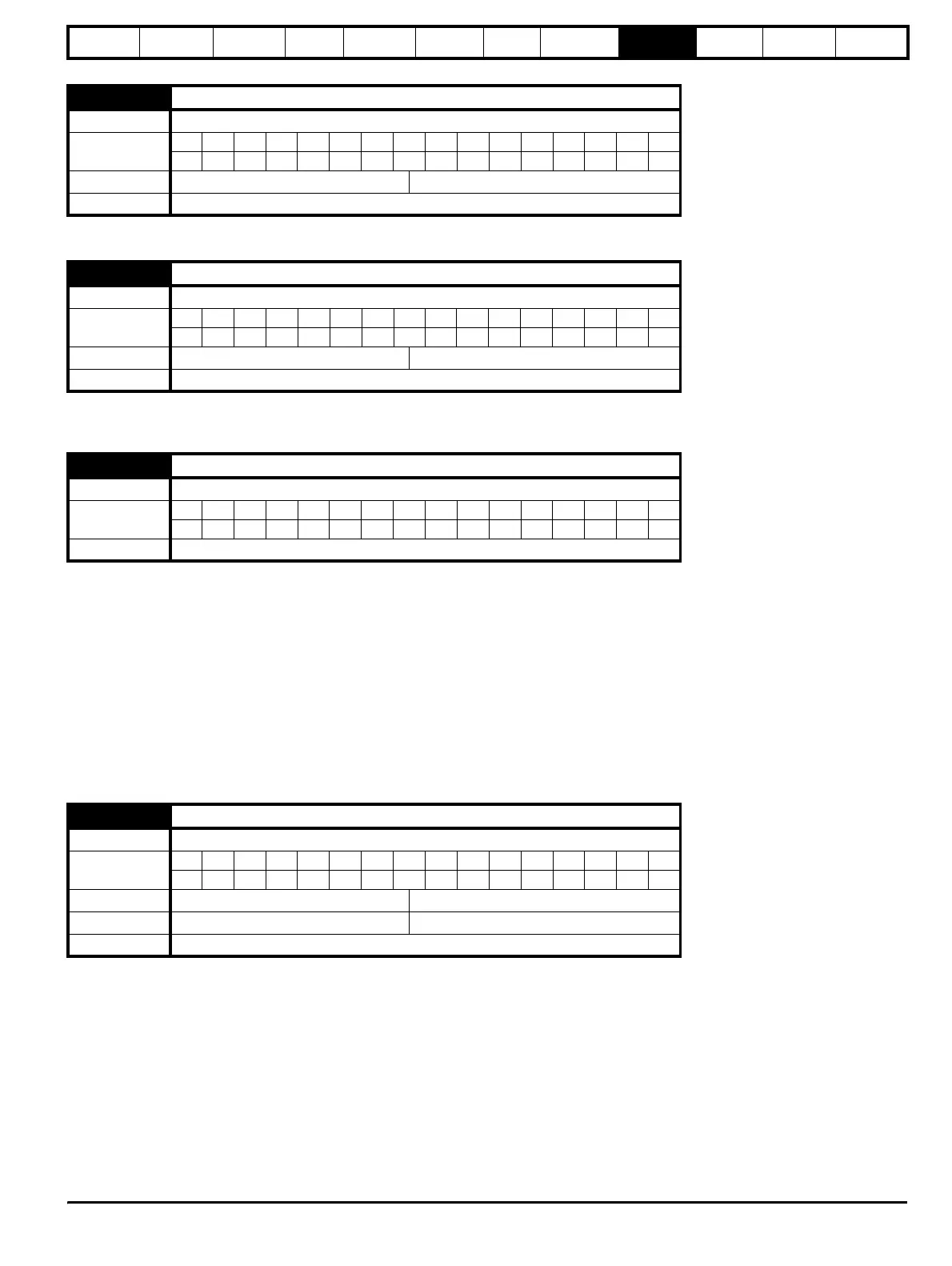
6.27 Time before filter change due
Drive mode Regen
Coding
Bit SP FI DE Txt VM DP ND RA NC NV PT US RW BU PS
111 11
Range Regen 0 to 30,000 hrs
Update rate Background
6.28 Select clock for trip log time stamping
Drive mode Regen
Coding
Bit SP FI DE Txt VM DP ND RA NC NV PT US RW BU PS
111
Default Regen 0
Update rate Background
6.29 Hardware enable
Drive mode Regen
Coding
Bit SP FI DE Txt VM DP ND RA NC NV PT US RW BU PS
111
Update rate 4ms
6.41 Drive event flags
Drive mode Regen
Coding
Bit SP FI DE Txt VM DP ND RA NC NV PT US RW BU PS
111
Range Regen 0 to 65535
Default Regen 0
Update rate Background