Unidrive M / HS Frame 7 to 10 Power Installation Guide 15
Issue Number: 5
Safety information
Product information
Mechanical installation Electrical installation Technical data UL listing information
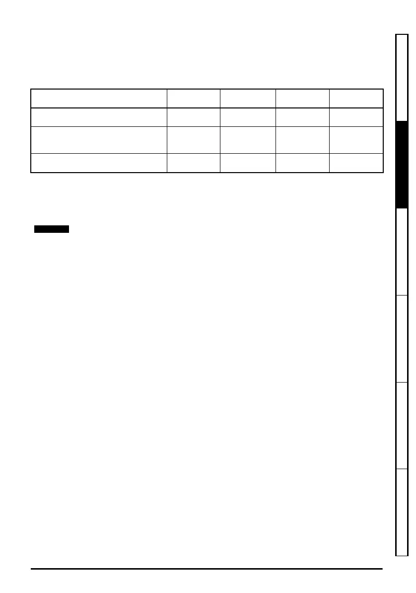
Typical short term overload limits
The maximum percentage overload limit changes depending on the selected motor. Variations in
motor rated current, motor power factor and motor leakage inductance all result in changes in the
maximum possible overload. Typical values are shown in the table below:
Table 2-6 Typical overload limits
Generally the drive rated current is higher than the matching motor rated current allowing a higher
level of overload than the default setting.
The time allowed in the overload region is proportionally reduced at very low output frequency on
some drive ratings.
Output current
The continuous output current ratings given on the rating label are for maximum 40 °C (104 °F),
1000 m altitude and 3 kHz switching frequency (except where shown). Derating is required for higher
switching frequencies, ambient temperatures >40 °C (104 °F) and higher altitude. For derating
information, refer to Chapter 5 Technical data on page 88
Input current
The input current is affected by the supply voltage and impedance. The input current given on the
rating label is the typical input current and is stated for a balanced supply.
Operating mode RFC from cold RFC from 100 %
Open loop
from cold
Open loop
from 100 %
Normal Duty overload with motor rated
current = drive rated current
110 % for 165 s 110 % for 9 s 110 % for 165 s 110 % for 9 s
Heavy Duty overload with motor rated
current = drive rated current (size 8 and
below)
200 % for 28 s 200 % for 3 s 150 % for 60 s 150 % for 7 s
Heavy Duty overload with motor rated
current = drive rated current (size 9 and 10)
175 % for 42 s 175 % for 5 s 150 % for 60 s 150 % for 7 s
The maximum overload level which can be attained is independent of the speed.
Unidrive M frame7 to 10 Power Installation Guide issue5.book Page 15 Tuesday, May 24, 2016 11:52 AM

 Loading...


