Unidrive M / HS Frame 7 to 10 Power Installation Guide 77
Issue Number: 5
Safety information Product information Mechanical installation
Electrical installation
Technical data UL listing information
Cable layout
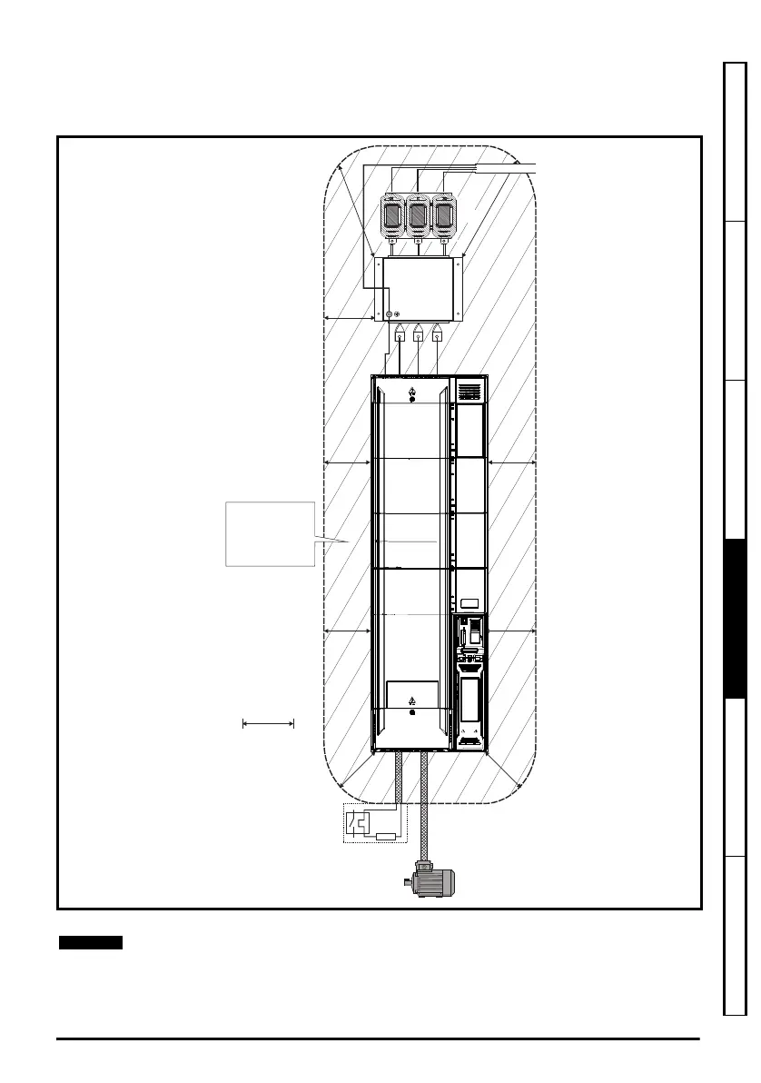
Figure 4-16 indicates the clearances which should be observed around the drive and related ‘noisy’
power cables by all sensitive control signals / equipment.
Figure 4-16 Drive cable clearances
Any signal cables which are carried inside the motor cable (i.e. motor thermistor, motor
brake) will pick up large pulse currents via the cable capacitance. The shield of these
signal cables must be connected to ground close to the motor cable, to avoid this noise
current spreading through the control system.
Optional braking
resistor and overload
Do not place sensitive
(unscreened) signal circuits
in a zone extending
300mm (12”) all around the
Drive, motor cable, input
cable from filter andEMC
unscreened braking resistor
cable (if used)
300mm
(12in)
INL 1
Unidrive M frame7 to 10 Power Installation Guide issue5.book Page 77 Tuesday, May 24, 2016 11:52 AM

 Loading...


