Unidrive M / HS Frame 7 to 10 Power Installation Guide 93
Issue Number: 5
Safety information Product information Mechanical installation Electrical installation
Technical data
UL listing information
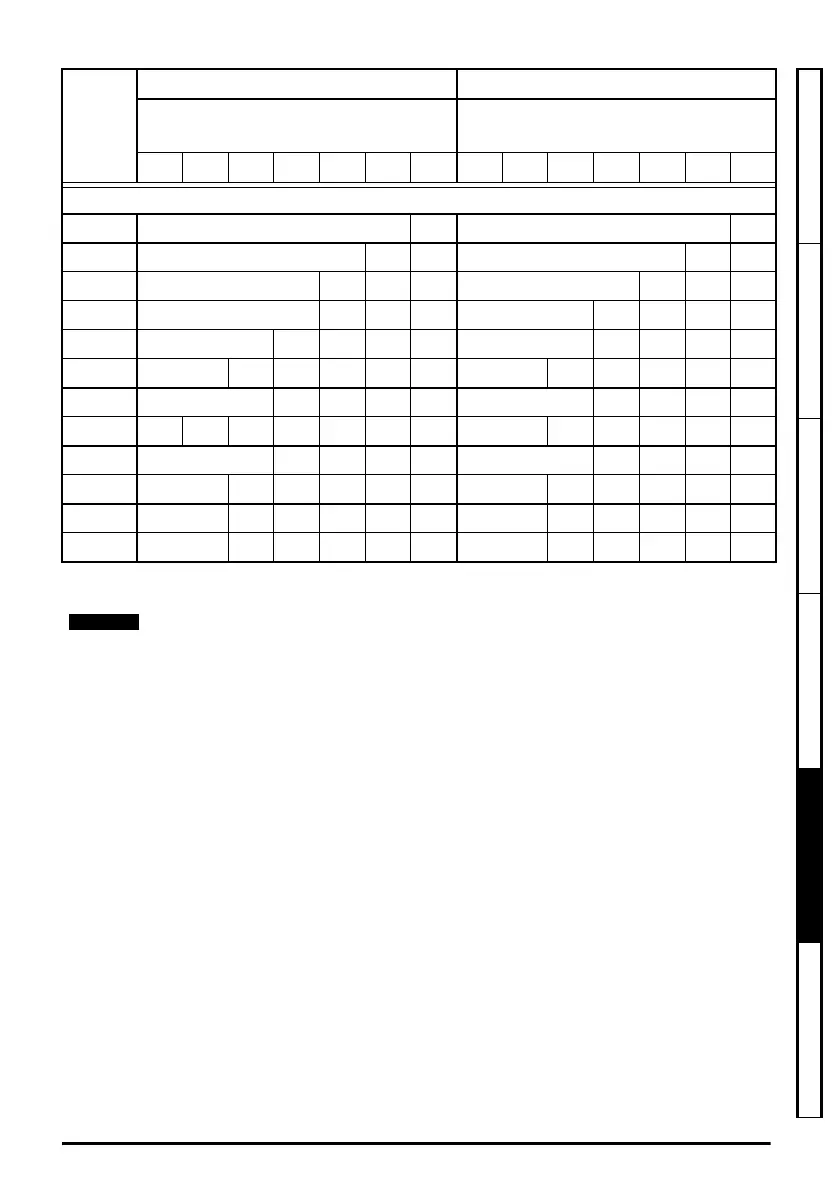
* For Unidrive M200 to M400 the 0.667 and 1 kHz value is the same as the 2 kHz value.
690 V
07600190 23 19 19 14.5
07600240 30 24.8 19 24 19.4 14.5
07600290 36 35.8 24.8 19 29 27.7 19.4 14.5
07600380 46 35.8 24.8 19 38 35.3 27.7 19.4 14.5
07600440 52 46.7 35.8 25 19 44 35.6 27.7 19.4 14.5
07600540 73 65 46.7 35.8 25 19 54 48.1 35.6 27.7 19.4 14.6
08600630 86 76.7 64.5 44.3 31.3 63 61.1 48.2 33.4 24.9
08600860 104 97.2 90.7 76.7 64.8 44.3 31.3 86 80.8 61.1 48.2 33.5 24.9
09601040 125 114 90 62 48 104 97 77 55 42
09601310 155 153 113 89 62 48 131 127 97 77 55 42
10601500 172 153 114 89 62 48 150 128 96 78 56 42
10601780 197 195 134 102 67 48 178 171 125 94 62 44
55 °C ratings are available on request
Model
Normal Duty Heavy Duty
Maximum permissible continuous output
current (A) for the following
switching frequencies
Maximum permissible continuous output
current (A) for the following
switching frequencies
2
kHz*
3
kHz
4
kHz
6
kHz
8
kHz
12
kHz
16
kHz
2
kHz*
3
kHz
4
kHz
6
kHz
8
kHz
12
kHz
16
kHz
Unidrive M frame7 to 10 Power Installation Guide issue5.book Page 93 Tuesday, May 24, 2016 11:52 AM

 Loading...


