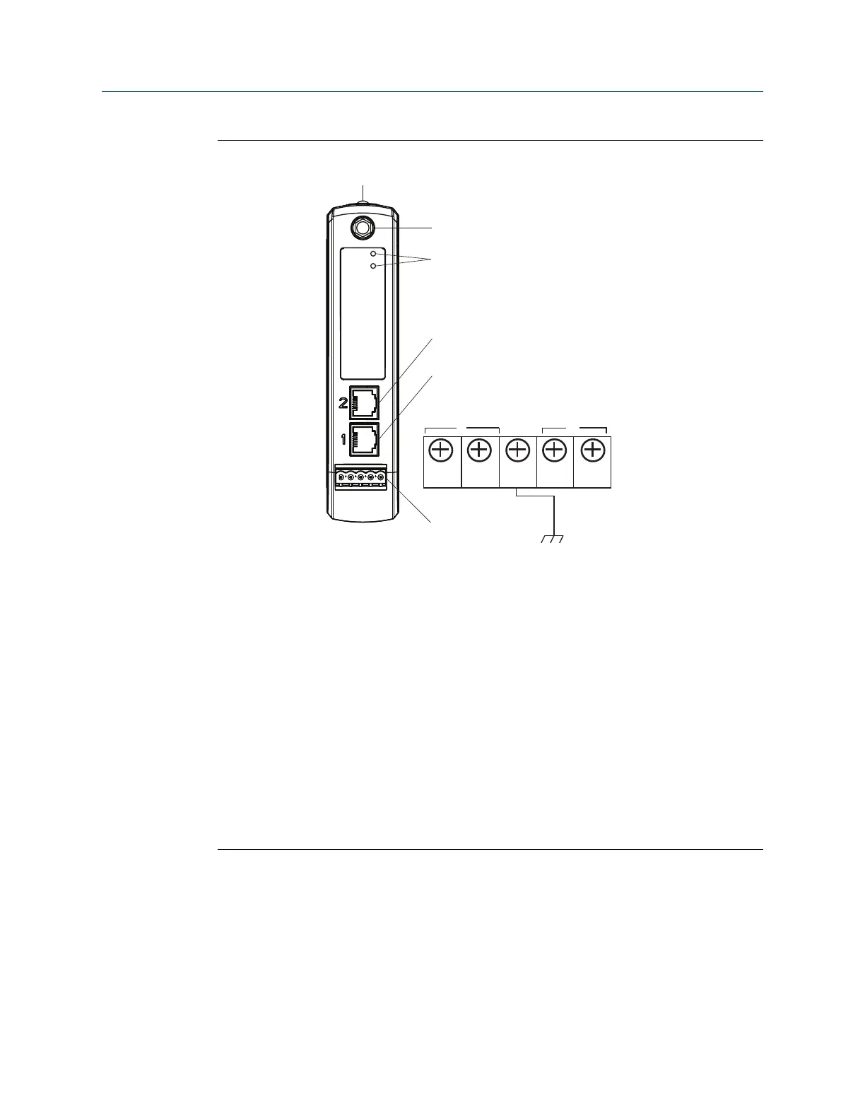
Figure 2-1: Emerson Smart Wireless Gateway 1410 Housing
+
- A B
G H
S
Power
Reset
A
B
C
D
E
F
A
DIN rail clip
B
SMA connector
C
Power and reset indicator lights: During normal operation the power indicator will be
green. During a reset the reset light will turn red. The reset switch should not be
enabled during normal operation.
D
Ethernet port 2:This secondary port must be enabled when ordering to access the
device. When this port is activated, the factory IP address is 192.168.2.10. See Table
2-1.
E
Ethernet port 1: Use for standard communication to the webserver or other protocols
enabled on the gateway. The factory IP address is 192.168.1.10. See Table 2-1.
F
5-screw terminal block
G
24 VDC (nominal) power input
H
Serial Modbus
®
2.3.3 Configure the gateway
It is now possible to log into the Gateway for the first time and begin configuration for
placement on a live control network. The following items need to be configured:
• Security Passwords
• Time Settings
• TCP/IP Network Settings
Reference Manual Configuration
00809-0200-4410 September 2020
Emerson.com/Rosemount 9

 Loading...

