recommended that the power selection mode switch be left in the PD position unless PSE
is needed.
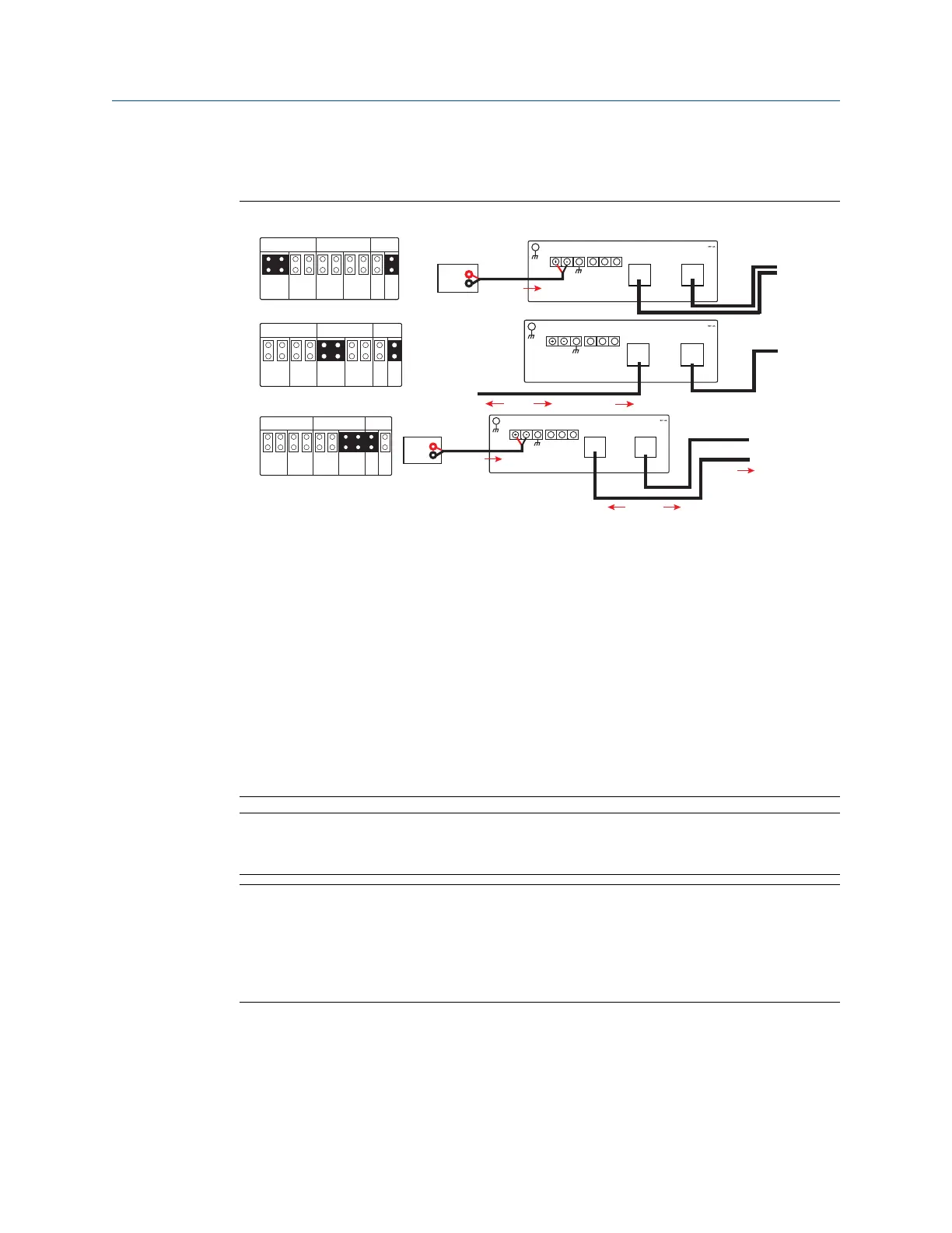
Figure 2-3: Gateway PoE Jumpering
P D P DP S E
E T H 1 E T H 2 P S E
P S E
E N
D I S
S
A
B
Case
Ethernet 2
Ethernet 1
To Host
Power
Modbus10.5V-30V
Input Power
S
A
B
Modbus10.5V-30V
Input Power
Case
Ethernet 2
Ethernet 1
From PSE Device
Power
P D P DP S E
E T H 1 E T H 2 P S E
P S E
E N
D I S
To Host
Data
P D P DP S E
E T H 1 E T H 2 P S E
P S E
E N
D I S
Power
S
A
B
Case
Ethernet 2
Ethernet 1
To Host
To POE Device
Power
Modbus10.5V-30V
Input Power
Data
Traditionally powered Gateway
PoE, Gateway as a PD via Ethernet Port 2
PoE, Gateway as a PSE via Ethernet Port 2
• ETH1: Ethernet port 1 selected for PD or PSE
• ETH2: Ethernet port 2 selected for PD or PSE
• PD: Gateway derives power from the Ethernet port selected
• PSE: Gateway derives power from a local power supply and sends power down the
Ethernet port selected to another device
• EN: Enabled; this enables the PSE operation
• DIS: Disabled; this disables the PSE operation
Note
Only one port and one mode of operation (PD or PSE) can be selected at a time; any other
combination of jumpers is invalid.
Note
IEEE 802.3af-2003 PoE standard provides up to 15.4 W of DC power (minimum 44 V DC
and 350 mA) to each device. Only 12.95 W is assured to be available at the powered device
as some power is dissipated in the cable. IEEE 802.3at-2009 PoE standard also known as
“PoE+” or “PoE plus”, provides up to 25.5 W of power. The 2009 standard prohibits a
powered device from using all four pairs for power.
For more information on PoE and frequently asked questions, refer to Emerson Wireless
1420 Gateway with Power over Ethernet Technical Note or Power over Ethernet (PoE).
In order to use both ports for PoE, remember to order option code “2” when selecting
number of Ethernet ports.
Reference Manual Configuration
00809-0200-4420 September 2020
Emerson.com/Rosemount 11

 Loading...

