Example
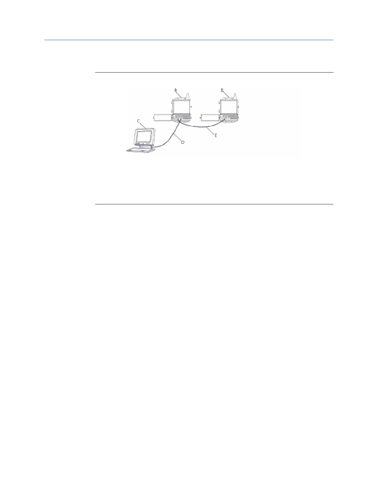
Figure D-3: Redundancy Setup Connections
A. Gateway A
B. Gateway B
C. PC/Laptop
D. Primary Ethernet
E. Secondary Ethernet
Once the Gateways have finished the pairing process, Gateway A will appear as the current
active Gateway on the left hand side and Gateway B will be the standby Gateway on the
right (note that left/right hand appearance can be changed on the Redundancy System
Settings page). If significant configuration changes need to be downloaded to the standby
Gateway, it may temporarily go offline shortly after the pair process is complete. This is
expected behavior and does not represent instability in the system.
D.4 Mounting and connections
Redundant Gateways follow similar mounting and connection practices as a standalone
Gateway. Refer to Installation for more information. In addition to the standard practices,
the following considerations should be taken when installing redundant Gateways.
D.4.1
Mounting
The redundant Gateways should be mounted in a location that allows convenient access
to the process control network as well and provides good coverage for the wireless field
network.
The redundant Gateway antennas should be mounted at the same height and be spaced
between 3–9 ft. (1–3 m) horizontally. This is to ensure that they provide identical coverage
for the wireless field network and to help eliminate coverage gap in the event of a switch
over.
D.4.2
Ethernet
An Ethernet connection to the host system will support Modbus TCP, OPC, AMS
™
Wireless
Configurator, and HART-IP
™
protocols. When using this architecture, connect the
secondary Ethernet port on Gateway A directly to the secondary Ethernet port on Gateway
B. Then connect the primary Ethernet ports for both Gateways to a process control
Redundancy
Reference Manual
September 2020 00809-0200-4420
88 Emerson.com/Rosemount

 Loading...

