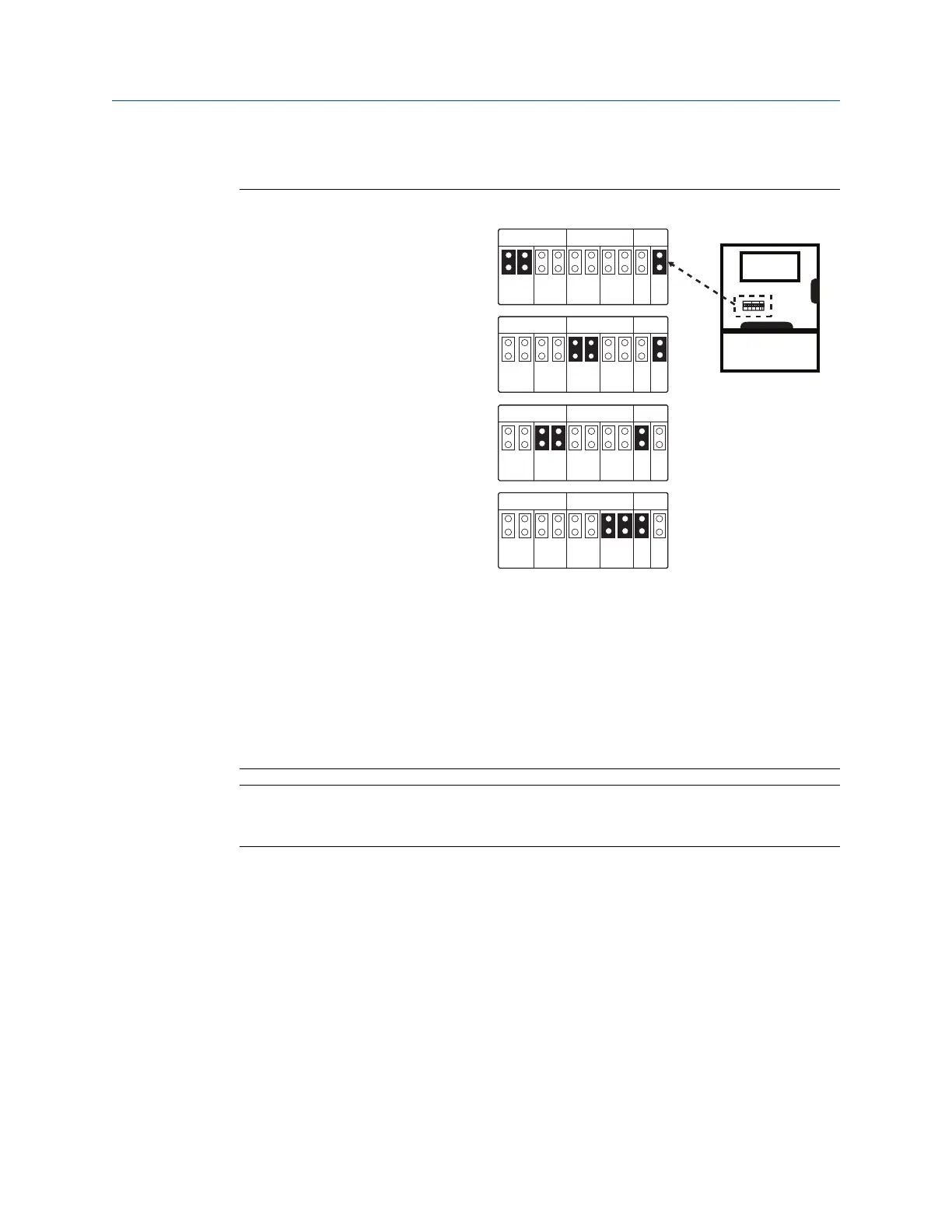
Gateway PoE jumpering
Figure 3-11: Jumpering Matrix Located on Gateway Main Board
P D P DP S E
E T H 1 E T H 2 P S E
P S E
E N
D I S
P D P DP S E
E T H 1 E T H 2 P S E
P S E
E N
D I S
P D P DP S E
E T H 1 E T H 2 P S E
P S E
E N
D I S
P D P DP S E
E T H 1 E T H 2 P S E
P S E
E N
D I S
PD PDPS E
E TH 1 E TH 2 PS E
PS E
EN
DI S
Computer
board
1420
with PoE
PoE PD on port 1
(Default jumpering for Production.
Used for no PoE also)
PoE PD on port 2
PoE PSE on port 1
PoE PSE on port 2
• ETH1: Ethernet port 1 selected for PD or PSE
• ETH2: Ethernet port 2 selected for PD or PSE
• PD: Gateway gets its power off the Ethernet port selected
• PSE: Gateway gets its power from a local power supply and sends power down the
Ethernet port selected to another device
• EN: Enabled; this enables the PSE operation
• DIS: Disabled; this disables the PSE operation
Note
Only one port and one mode of operation (PD or PSE) can be selected at a time. Any other
combination of jumpers is invalid.
Reference Manual Installation
00809-0200-4420 September 2020
Emerson.com/Rosemount 33

 Loading...

