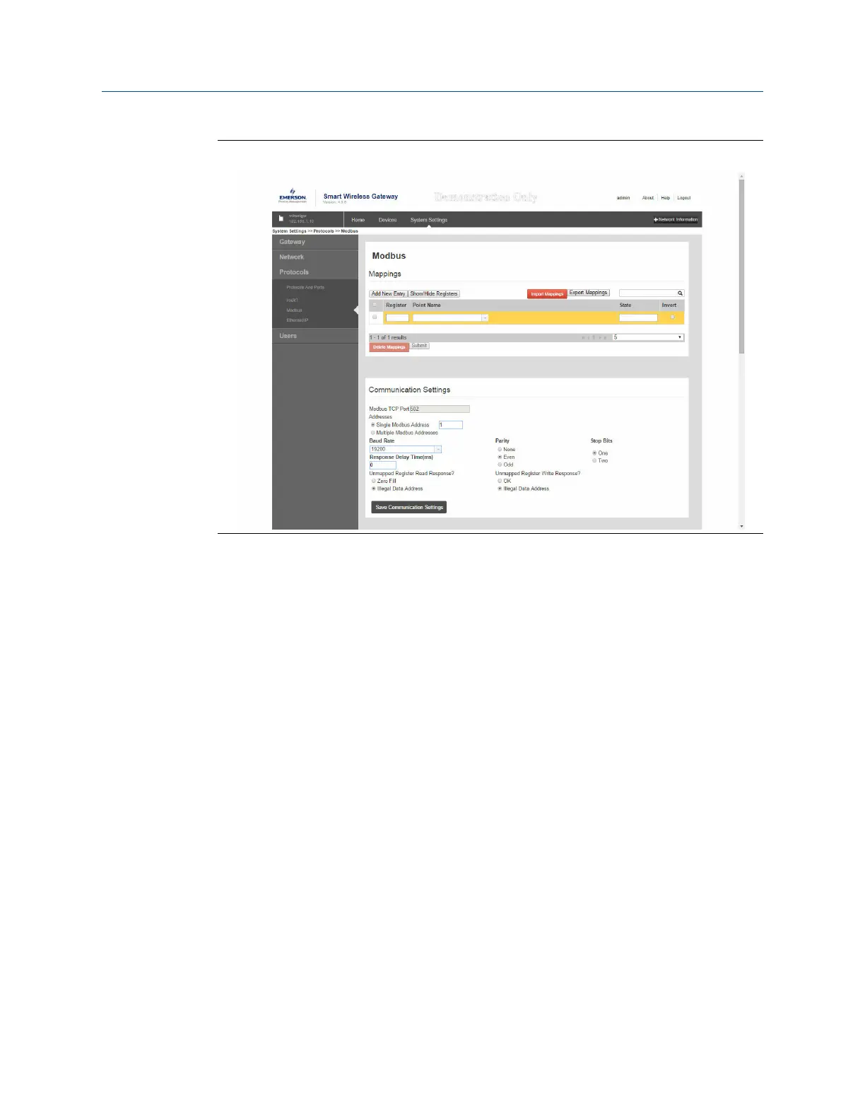
Figure 5-6: Modbus Register Map Page
To add a new data point to the Modbus register map:
Procedure
1. Select Add New entry.
2. Complete all of the table entries for the new data point (note that the entry
columns may vary based on the Modbus communications settings).
3. Repeat for each new data point.
4. Select Submit.
Example
Address: This is the Modbus RTU address used by the Gateway for this data point. It is
possible to group data points assigning them the same address (i.e. all data points from
the same process unit can have the same address). This column only appears if Multiple
Modbus Addresses is selected on the Modbus Communications page.
Register: This is the Modbus register number used for this data value. Modbus registers
hold two bytes (16 bits) of information; therefore 32 bit floats and integers require two
Modbus registers. Each data point needs a unique Modbus register number, unless they
are assigned different addresses. Register numbers 0-19999 are reserved for Boolean (bit,
coil, binary, etc…) values. Register numbers 20000+ are reserved for floating point or
integer values.
Point Name: This is a two part name for the data point. The first part is the HART Tag of the
wireless field device which is producing the data. The second part is the parameter of the
wireless field device.
Operation and Maintenance Reference Manual
September 2020 00809-0200-4420
50 Emerson.com/Rosemount

 Loading...

